
Advertisements
Fuse box diagram (fuse layout), location, and assignment of fuses and relays Kia Carens (UN) (2006, 2007, 2008, 2009, 2010, 2011, 2012, 2013).

Checking and Replacing Fuses
A vehicle’s electrical system is protected from electrical overload damage by fuses. If any of your vehicle’s lights, accessories, or controls do not work, check the appropriate circuit fuse. If a fuse has blown, the element inside the fuse will be broken or melted. Check those fuses first that protect the failed component, but check all the fuses before deciding that a blown fuse is not the cause. Replace any blown fuses with another with the same amperage (same color) and check the component’s operation.
Notice
- Before changing a fuse, check the ignition key has been removed and that all the other electric devices have been turned off/disabled.
- Do not use a screwdriver or any other metal object to remove fuses because it may cause a short circuit and damage the system.
- Never replace a fuse with anything but another fuse of the same rating. A higher capacity fuse could cause damage and possibly a fire. Never install a wire or aluminum foil instead of the proper fuse even as a temporary repair. It may cause extensive wiring damage and a possible fire.
- If the replacement fuse blows, this indicates an electrical problem. Avoid using the system involved and immediately consult at a qualified service center.
- When replacing a blown fuse or relay, make sure the new fuse or relay fits tightly into the clips. Failure to tightly install the fuse or relay may cause damage to the wiring and electric systems.
- If you do not have a spare, use a fuse of the same rating from a circuit you may not need for operating the vehicle, such as the cigarette lighter fuse.
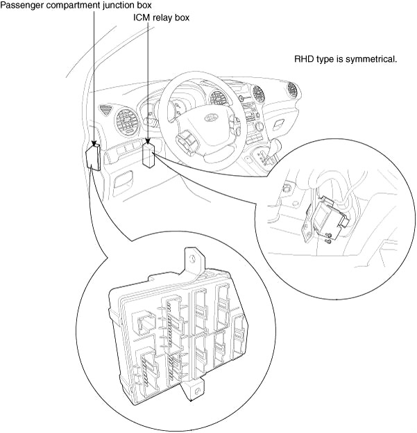
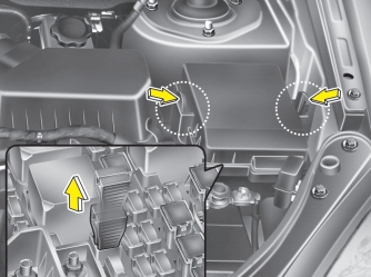
Location
This vehicle has 2 (or 3) fuse panels, one located in the driver’s side panel bolster, the other in the engine compartment near the battery.
- Horn relay
- Headlamp relay (Low-left side)
- Headlamp relay (High)
- Cooling pan relay (High)
- Cooling pan relay (Low)
- Fuel pump relay
- Main relay
- Wiper relay
- A/C relay
- Start relay
- Glow relay
- PTC heater relay #1
- PTC heater relay #2
- PTC heater relay #3
- Fuel filter heater relay
Advertisements
Instrument Panel Fuse Box
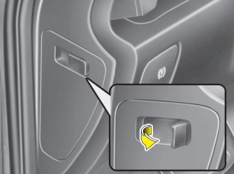
The fuse panel is behind the cover on the driver’s side dash panel.
To check and replace a fuse:
- Turn the ignition switch and all other switches off.
- Open the fuse panel cover.
- Pull the suspected fuse straight out. Use the removal tool provided on the engine compartment fuse panel cover.
- Check the removed fuse; replace it if it is blown. Spare fuses are provided in the inner fuse panel (or in the engine compartment fuse panel).
- Push in a new fuse of the same rating, and make sure it fits tightly in the clips.
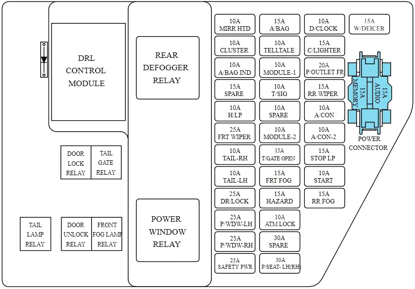
| Fuse | A | Circuit Protected |
|---|---|---|
| HEAD LP | 10 | Head lamp relay, AQS sensor, HLLD actuator, PTC heater relay, Fuel filter heater relay |
| FRT. WIPER | 25 | Wiper relay, Wiper motor, Multifunction switch |
| FRT.FOG | 15 | Front fog lamp relay |
| DR.LOCK | 25 | Door lock/unlock relay |
| HAZARD | 15 | Hazard switch, Hazard relay |
| T.GATE | 15 | Fuel filler door switch, Tail gate relay |
| MIRR.HTD | 10 | Outside mirror motor & Defogger, A/C control module |
| MODULE-2 | 10 | Sunroof, Rain sensor, Seat warmer relay, Electro chromic mirror, BCM |
| A.CON | 10 | A/C control module, Blower relay |
| A/CON-2 | 10 | A/C Control Module (Auto) |
| RR.WIPER | 15 | Rear wiper motor, Rear wiper relay, Multifunction switch |
| STOP LP | 15 | Stop lamp switch |
| ATM K/LOCK | 10 | Sport mode switch, Data link connector, A/C control module, Multipurpose check connector |
| START | 10 | Burglar alarm relay |
| RR.FOG | 15 | Rear fog lamp relay |
| W.DEICER | 15 | Windshield defogger relay |
| P-OUTLET-FRT | 20 | Front power outlet |
| SAFETY PWR | 25 | Safety window motor |
| PSEAT-LH/RH | 30 | Driver power seat manual switch |
| TAIL RH | 10 | Head lamp RH, Rear combination lamp RH, License lamp, DRL control module |
| A.BAG IND | 10 | Instrument cluster |
| CLUSTER | 10 | Instrument cluster, Pre-excitation resistor |
| C.LIGHTER | 15 | Cigarette lighter |
| P.WDW-RH/LH | 25 | Power window main switch, Power window switch RH/LH |
| P.WDW-LH/RH | 25 | Power window main switch, Power window switch LH/RH |
| TAIL LH | 10 | Head lamp LH, Rear combination lamp LH, Front fog lamp relay |
| A. BAG | 15 | SRS control module |
| MODULE-1 | 10 | ATM key lock control module, Back warning buzzer, ESP switch, BCM, Auto light control module |
| TELL TAIL | 10 | Digital clock, PAB cut off switch |
| T.SIG | 10 | Hazard switch |
| D.CLOCK | 10 | Power outside mirror switch, Audio, BCM, Digital clock, ATM key lock control module |
| AUDIO | 15 | Audio |
| MEMORY | 15 | BCM, Key ill. switch, Digital clock, Mirror folding relay, Instrument cluster, Room lamp, A/C control module |
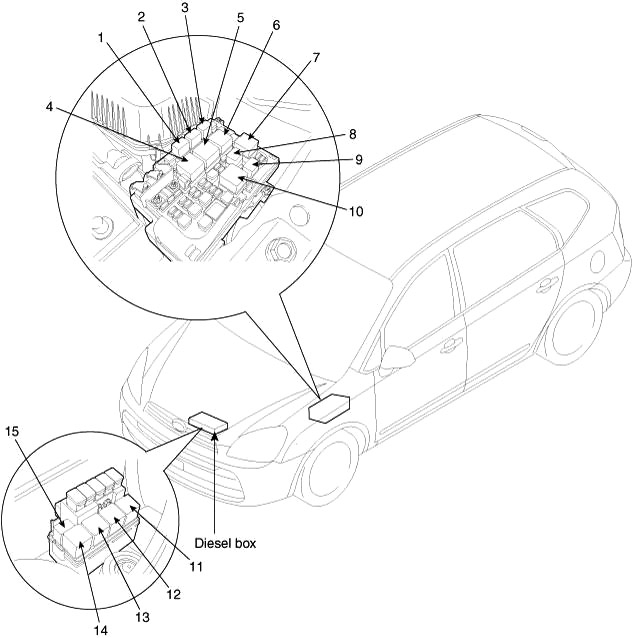
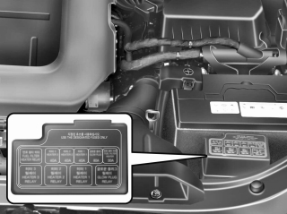
Relay Box
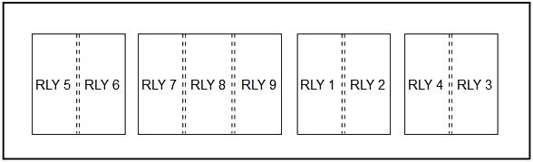
| № | Circuit Protected |
|---|---|
| 1 | - |
| 2 | SEAT WARMER |
| 3 | REAR FOG LAMP |
| 4 | RAIN SENSOR |
| 5 | MIRROR FOLDING |
| 6 | WINDSHIELD DEFOGGER |
| 7 | HAZARD |
| 8 | BURGLAR HORN |
| 9 | BURGLAR ALARM |
Advertisements
Engine Compartment Fuse Box
To check and replace a fuse:
- Turn the ignition switch and all other switches off.
- Remove the fuse panel cover by pressing the tab and pulling up.
- Check the removed fuse; replace it if it is blown. To remove or insert the fuse, use the fuse puller in the engine compartment fuse panel.
- Push in a new fuse of the same rating, and make sure it fits tightly in the clips. If it fits loosely, consults an authorized Kia dealer.
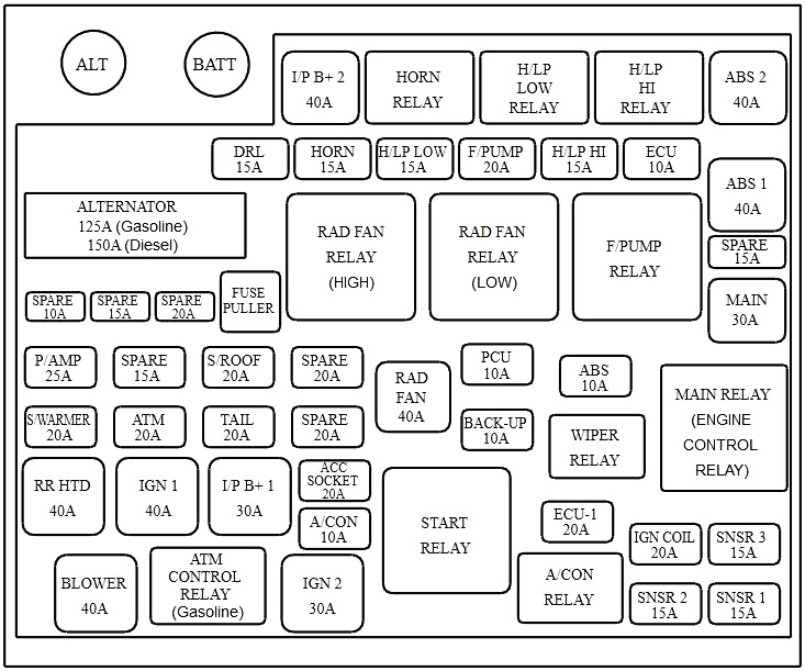
| Fuse | A | Circuit Protected |
|---|---|---|
| ALTERNATOR | 125 | Gasoline: Generator |
| 150 | Diesel: Generator | |
| l/P B+2 | 40 | l/P Junction box |
| ABS 2 | 40 | ABS/ESP control module |
| ABS 1 | 40 | ABS/ESP control module |
| BLOWER | 40 | Blower relay |
| RR HTD | 40 | Rear defogger relay |
| IGN 1 | 40 | Ignition switch(ACC, IG1) |
| RAD FAN | 40 | Radiator fan relay(LOW)/(HIGH) |
| MAIN | 30 | Engine control relay |
| IGN 2 | 30 | Ignition switch(IG2, START), Start relay |
| l/P B+1 | 30 | l/P Junction box |
| S/WARMER | 20 | Seat warmer relay |
| ACC SOCKET | 20 | Rear power outlet |
| ATM | 20 | ATM control relay |
| S/ROOF | 20 | Sunroof control module |
| P/AMP | 25 | Amp |
| F/PUMP | 20 | Fuel pump relay |
| IGN COIL | 20 | Ignition coil(Gasoline) |
| ECU-1 | 20 | ECM |
| TAIL | 20 | Tail lamp relay |
| DRL | 15 | DRL control module |
| HORN | 15 | Horn relay, Burglar horn relay |
| H/LP LOW | 15 | Head lamp relay (Low) |
| H/LP HI | 15 | Head lamp relay (High) |
| SNSR 1 | 15 | D4EA: Immobilizer Control Module, Camshaft Position Sensor, Throttle Control Actuator |
| D4FB: Camshaft Position Sensor, Immobilizer Control Module | ||
| G4KA:Mass Air Flow Sensor, Canister Purge Solenoid Valve, Camshaft Position Sensor, Crankshaft Position Sensor,Idle Speed Control Actuator, Immobilizer Control Module, Oil Control Valve | ||
| G4FC: Injector #1~#4, Immobilizer Control Module | ||
| SNSR 2 | 15 | D4EA: EGR Actuator, Fuel Pump Relay, Fusible Link Box (GLOW PLUG RELAY, PTC HEATER RELAY #1) |
| D4FB: VGT Actuator, Fuel Pressure Regulating Valve, Fuel Pump Relay, Fusible Link Box (GLOW PLUG RELAY, PTC HEATER RELAY #1) | ||
| G4KA: Fuel Pump Relay, Front/Rear Oxygen Sensor | ||
| G4FC: Fuel Pump Relay, Idle Speed Control Actuator, Oil Control Valve | ||
| SNSR 3 | 15 | D4EA: A/CON Relay, Lambda Sensor, Rad Fan (HI/LOW) Relay, Stop Lamp Switch |
| D4FB: Stop Lamp Switch, EGR Cooling Bypass Solenoid, Lambda Sensor, A/CON Relay, Rad Fan (HI/LOW) Relay | ||
| G4KA: Injector #1~#4, A/CON Relay | ||
| G4FC: Oxygen Sensor (Up/Down), Camshaft Position Sensor, A/CON Relay, Purge Control Solenoid Valve | ||
| ECU | 10 | TCM (D4EA), Alternator (D4EA), ECM (G4KA, G4FC M/T) |
| PCU | 10 | ECM/PCM, Rad Fan (HI/LOW) Relay (G4KA, G4FC), Pulse Generator 'A' 'B', Air Flow Sensor (D4EA/D4FB),Stop lamp switch (G4KA, G4FC), Fuel Filter Warning Sensor (D4EA/D4FB) |
| ABS | 10 | ABS/ESP control module, Multipurpose check connector |
| BACK-UP | 10 | Vehicle speed sensor, Back-up lamp switch, Transaxle range switch |
| A/CON | 10 | A/C relay |
Additional Fuse Box (Diesel)
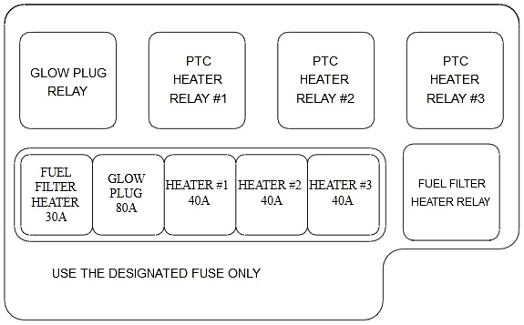
| Fuse | A | Circuit Protected |
|---|---|---|
| FUEL FILTER HEATER | 30 | Fuel filter heater relay |
| GLOW PLUG | 80 | Glow plug relay |
| HEATER #1 | 40 | PTC heater relay #1 |
| HEATER #2 | 40 | PTC heater relay #2 |
| HEATER #3 | 40 | PTC heater relay #3 |
Main fuse
If the main fuse is blown, it must be removed as follows:
- Turn off the engine.
- Disconnect the negative battery cable.
- Remove the nuts shown in the picture above.
- Replace the fuse with a new one of the same rating.
- Reinstall in the reverse order of removal.
Advertisements