
Advertisements
Fuse box diagram (fuse layout), location, and assignment of fuses Jaguar F-Type (2014, 2015, 2016, 2017).

Checking and Replacing Fuses
If an electrical system has stopped operating, the cause may be a blown fuse. The easiest way to check if a fuse has blown is to first remove it.
To check for a blown fuse:
- Refer to the fuse box tables shown in this section to identify the correct fuse.
- Gain access to the appropriate fuse box.
- Refer to the fuse box label to locate the correct fuse. Depending on the fuse box, the label is located on the underside of the lid.
- Use the fuse removal tool to remove the fuse.
- Check for a break in the wire within the fuse. If the wire within the fuse is broken, the fuse has blown and needs replacing. If the wire is still intact, consult a retailer/authorized repairer. Spare fuses and the fuse removal tool are located in the passenger side footwell fuse box.
- Refit or replace the fuse, as appropriate. Make sure the fuse is pushed fully into its correct position.
Notice
- Always switch off the ignition system and the affected electrical circuit before replacing a fuse. Failure to do so could cause damage to the vehicle.
- Never replace a broken fuse with anything other than a new fuse. Always use a fuse of the same colour.
- Never change a fuse with another amperage. This can cause damage to the electrical system and fire.
- If the replacement fuse blows after installation, the system should be checked by a Retailer/Authorized Repairer.
Fuse box locations
There are 6 separate fuse boxes fitted to the vehicle, each one containing fuses protecting a different group of circuits.
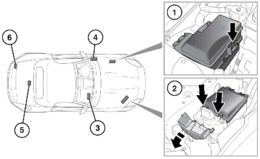
- Engine compartment left side fuse box:
Remove the left side underhood cover, press the clip to release the fuse box cover.
- Engine compartment right side fuse box:
Open the side cover and press the 2 clips to release the fuse box cover.
- Passenger compartment fuse box, located in the passenger side footwell:
Pull back the floor mat/carpet to reveal the access panel. Pull up and remove the access panel to view the fuse box.
- Passenger compartment fuse box, located on the left side A-pillar, below the facia:
Unclip the access panel to view the fuse box.
- Coupe vehicles only:
The fuse box is accessed by: Folding back the luggage compartment floor panel and removing the floor panel support block. Removing the left side luggage compartment (battery) cover. Removing the luggage floor well trim.
- Convertible vehicles only.
The fuse box is accessed by: Removing the left side luggage compartment (battery) cover. Removing the luggage floor well trim.
Under-hood covers removal:
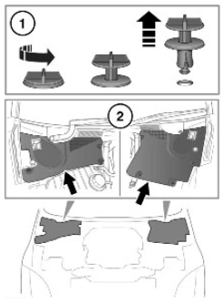
- Rotate the turnbuckle screws counterclockwise, then pull to remove.
- Lift the front edge of the cover and slide forward to remove it.
- Refit these parts in the reverse order of removal.
Advertisements
Passenger Compartment Fuse Boxes
Left-side A-pillar fuse box diagram
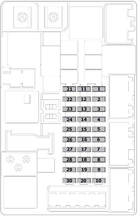
| № | Amp | Circuit |
|---|---|---|
| F1 | 30A | Electric Parking Brake (EPB) (left side) |
| F2 | - | - |
| F3 | - | - |
| F4 | - | - |
| F5 | 10A | Instrument panel control, Instrument panel fan |
| F6 | 15A | Convertible roof (front latch) |
| F7 | - | - |
| F8 | 5A | Keyless vehicle module (logic) |
| F9 | 15A | Convertible roof (down lock) |
| F10 | 10A | Air conditioning clutch |
| F11 | 25A | Heated front seat |
| F12 | 5A | Seat switch power |
| F13 | 10A | Chassis control module (spoiler), JaguarDrive control switch |
| F14 | - | - |
| F15 | 25A | Tailgate |
| F16 | 30A | Electric Parking Brake (EPB) (right side) |
| F17 | 10A | Adaptive damping control, Chassis control module |
| F18 | - | - |
| F19 | 30A | Fuel pump |
| F20 | - | - |
| F21 | 10A | Rear camera, Headlamps, Blind Spot Monitoring (BSM), Park Distance Control, Interior mirror |
| F22 | 5A | Right side headlamp motor |
| F23 | 5A | Left side headlamp motor |
| F24 | 5A | Headlamp leveling |
| F25 | 10A | Instrument panel control, Instrument panel fan |
| F26 | 5A | Gateway module |
| F27 | - | - |
| F28 | - | - |
| F29 | 10A | Rear camera, Headlamps, Blind Spot Monitoring (BSM), Park Distance Control, Interior mirror |
| F30 | 5A | Normal mode (or Transport mode) |
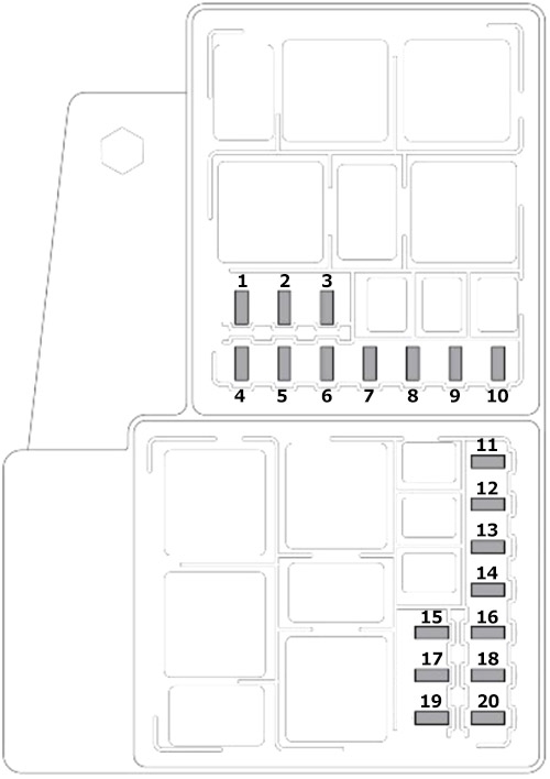
Passenger side foot-well fuse box diagram
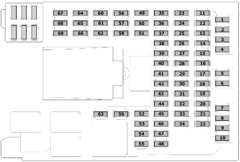
| № | Amp | Circuit |
|---|---|---|
| F1 | 5A | Radio Frequency (RF) receiver, Interior motion sensor, Tire pressure monitoring sensor (TPMS) |
| F2 | - | - |
| F3 | - | - |
| F4 | 5A | CAN gateway module |
| F5 | 5A | Anti-lock Braking System (ABS), Steering angle sensor |
| F6 | - | - |
| F7 | - | - |
| F8 | 30A | Right side seat (power 2) |
| F9 | 5A | Electric Parking Brake (EPB) |
| F10 | 5A | Adaptive damping control |
| F11 | - | - |
| F12 | 5A | Reverse lamps and Mirror dimming inhibit |
| F13 | - | - |
| F14 | 5A | Brake pedal switch |
| F15 | 30A | Heated rear screen |
| F16 | - | - |
| F17 | - | - |
| F18 | - | - |
| F19 | 5A | Powertrain control module, Electronic control module |
| F20 | 10A | Heated steering wheel |
| F21 | 10A | Passenger air bag disable lamp (overhead console) |
| F22 | 5A | Transmission control module, Rear differential, Electronic transmission switch (ignition signal) |
| F23 | 5A | Fuse box suppression |
| F24 | 5A | Right side rear fog lamp |
| F25 | 5A | Left side rear fog lamp |
| F26 | - | - |
| F27 | - | - |
| F28 | 25A | Door module (right side) |
| F29 | - | - |
| F30 | - | - |
| F31 | 5A | Rain sensor, Climate control sensors |
| F32 | 25A | Door module (left side) |
| F33 | - | - |
| F34 | 10A | Cubby box lock, Stowage box lock |
| F35 | - | - |
| F36 | - | - |
| F37 | - | - |
| F38 | 15A | Front screen washer |
| F39 | - | - |
| F40 | - | - |
| F41 | - | - |
| F42 | 30A | Left side seat (power 1) |
| F43 | 10A | Active exhaust |
| F44 | - | - |
| F45 | 30A | Right side seat (power 1) |
| F46 | 30A | Left side seat (power 2) |
| F47 | - | - |
| F48 | - | - |
| F49 | - | - |
| F50 | - | - |
| F51 | 5A | Steering wheel switches |
| F52 | 20A | Accessory socket (center) |
| F53 | 20A | Accessory socket/cigar lighter (cubby box) |
| F54 | - | - |
| F55 | - | - |
| F56 | 10A | Restraint control module |
| F57 | 10A | Glove box lamp, Reading lamps |
| F58 | - | - |
| F59 | 10A | Door soft close (close and reverse) |
| F60 | 5A | Occupant control sensor |
| F61 | 5A | Immobiliser antenna unit |
| F62 | - | - |
| F63 | - | - |
| F64 | - | - |
| F65 | - | - |
| F66 | - | - |
| F67 | - | - |
| F68 | - | - |
| F69 | - | - |
Advertisements
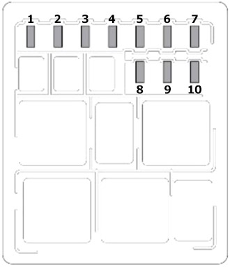
Engine Compartment Fuse Boxes
Left-side fuse box diagram
| № | Amp | Circuit |
|---|---|---|
| F1 | 5A | Diagnostic socket |
| F2 | 20A | Washer transfer pump |
| F3 | - | - |
| F4 | 5A | Monitor (Starter motor monitor) |
| F5 | 25A | Engine management (ignition coils) |
| F6 | 5A | Engine management (MAF sensors) |
| F7 | 5A | Engine management (sensors) |
| F8 | 10A | Engine management (actuators) |
| F9 | 10A | Engine management (throttle motor) |
| F10 | 15A | Engine management (variable valve timing) |
| F11 | 20A | Engine management (oxygen sensor-left side) |
| F12 | 20A | Engine management (oxygen sensor-right side) |
| F13 | 20A | Engine management (catalyst oxygen sensor) |
| F14 | 10A | Electric water pump |
| F15 | 5A | Active exhaust valve |
| F16 | - | - |
| F17 | 5A | Engine management system |
| F18 | 30A | Anti-lock Braking System (ABS)valves |
| F19 | 15A | Electronic transmission switch, Transmission control module |
| F20 | 30A | All Wheel Drive system |
Right-side fuse box diagram
| № | Amp | Circuit |
|---|---|---|
| F1 | 25A | Headlamp wash |
| F2 | - | - |
| F3 | 15A | Horns |
| F4 | - | - |
| F5 | - | - |
| F6 | - | - |
| F7 | - | - |
| F8 | - | - |
| F9 | - | - |
| F10 | - | - |
Luggage Compartment Fuse Box Diagram
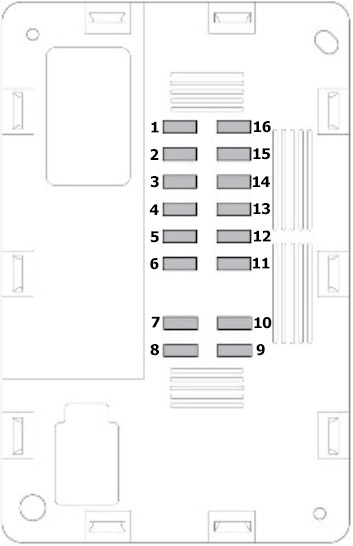
| № | Amp | Circuit |
|---|---|---|
| F1 | 15A | Touch screen, Front integrated control panel |
| F2 | 10A | Audio amplifier |
| F3 | - | - |
| F4 | 10A | Satellite radio, Navigation system |
| F5 | 15A | Audio head unit |
| F6 | 15A | Audio video input/output panel |
| F7 | - | - |
| F8 | - | - |
| F9 | - | - |
| F10 | - | - |
| F11 | - | - |
| F12 | - | - |
| F13 | - | - |
| F14 | - | - |
| F15 | 15A | Front integrated control panel (heating and ventilation) |
| F16 | - | - |
Advertisements