Advertisements
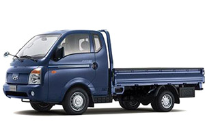
Fuse box diagram (fuse layout), location, and assignment of fuses and relays Hyundai Porter, H100 (HR; 2004, 2005, 2006, 2007, 2008, 2009, 2010, 2011, 2012, 2013, 2014, 2015, 2016).
Checking and Replacing Fuses
The wiring circuits in your vehicle are protected from short circuits by a combination of fuses, circuit breakers, and fusible links. This greatly reduces the chance of damage caused by electrical problems.
If any of your car’s lights or other electrical accessories stop working, a blown fuse could be the reason. If the fuse has burned out, you will see that the metal strip inside the fuse has burned through. Follow this procedure if you suspect a blown fuse:
- Turn off the ignition and all other switches.
- Open the fuse box and examine each fuse. Remove each fuse by pulling it toward you (a small “fuse puller” tool is contained in the fuse box to simplify this operation).
- Be sure to check all other fuses even if you find one that appears to have burned out.
- Replace the blown fuse by pressing a new fuse of the same rating into place. The fuse should be a snug fit. If it is not, have the fuse clip repaired or replaced by a Hyundai dealer. If you do not have a spare fuse, you may be able to borrow a fuse of the same or lower rating from an accessory you can temporarily get along without (the radio or cigarette lighter, for example). Always remember to replace the borrowed fuse.
Notice
- Never replace a broken fuse with anything other than a new fuse. Use always an intact fuse of the same color.
- If a fuse blows again contact a qualified service center.
Location
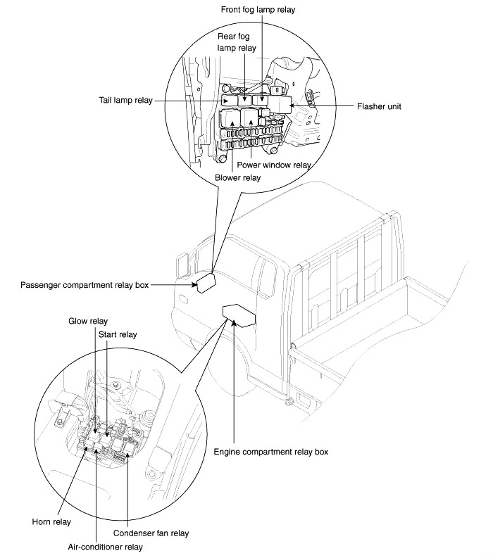
Instrument Panel Fuse Box Diagram
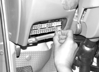
The fuse box will be found low on the dashboard on the driver’s side.
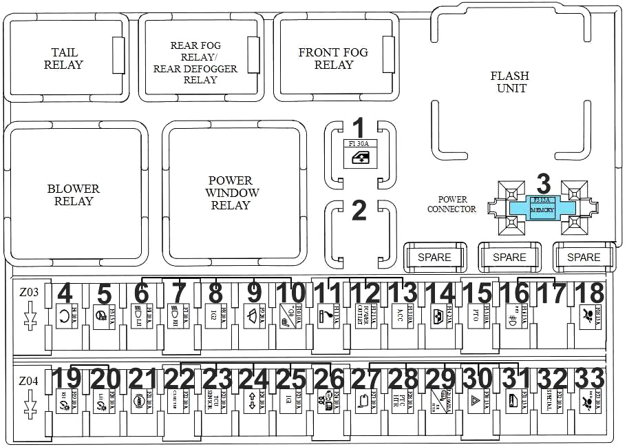
| № | A | Function/component |
|---|---|---|
| 1 | Power Window Relay | |
| 3 | 15 | Room Lamp, Door Warning Switch, Audio. ETACM, Instrument Cluster, Data Link Connector.Room Lamp (Double Cab) |
| 4 | 10 | Glow Control Module (D4BB). E/R Junction Box (RLY. 4) |
| 5 | 15 | - |
| 6 | 10 | Head Lamp LH, Instrument Cluster |
| 7 | 10 | Head Lamp RH |
| 8 | 10 | Heater Control Switch, ETACM. Head Lamp Leveling Switch. Blower Relay, Front Fog Lamp Relay, E/R Junction Box (RLY. 5), Head Lamp Leveling Actuator LH/RH |
| 9 | 20 | Wiper Motor, Multifunction Switch (INT) |
| 10 | 10 | Rear Foq Lamp Relay |
| 11 | 15 | Cigarette Lighter |
| 12 | 15 | - |
| 13 | 10 | Audio, ETACM |
| 14 | 25 | - |
| 15 | 10 | - |
| 16 | 15 | Front Fog Lamp Relay |
| 18 | 15 | Instrument Cluster. Driver Power Window Switch. Rear Defogger Switch, Head Lamp Leveling Switch, Heated Control Switch |
| 18 | 10 | Position Lamp RH, Rear Combination Lamp RH, License Lamp (Standard), Hazard Switch, Audio, Rear Detogger Switch, Heater Control Switch, Instrument Cluster, Head Lamp Leveling Switch, Driver Power Window Switch |
| 20 | 10 | Position Lamp LH, Rear Combination Lamp LH, License Lamp (Dual) |
| 21 | 10 | |
| 22 | 10 | Instrument Cluster. Pre-Excitation Resistor |
| 23 | 10 | ECM (D4BH/D4CB), Mass Air Flow Sensor (D4CB) |
| 24 | 10А | Hazard Switch (T/SIG), Back-Up Lamp Switch |
| 26 | 10 | ETACM |
| 26 | 10 | Fuel Cutoff Solenoid. Glow Control Module (D4BB). Fuel Filter Warning Sensor. EGR Solenoid Valve (D4BB). RLY. 3 (D4BB) |
| 27 | 10 | EGR Solenoid Valve, Mass Air Flow Sensor. Fuel Filter Warning Sensor (D4CB). Neutral Switch (D4BH) |
| 28 | 10 | Heated Control Switch |
| 29 | 10 15 | Rear Defogger Relay (D4BB) |
| 30 | 15 | Hazard Switch |
| 31 | 15 | Driver Door Lock actuator |
| 32 | 10 | Vehicle Speed Sensor. E/R Junction Box (Condenser Fan Relay) |
| 33 | 10 | Rear Defogger Relay |
Advertisements
Engine Compartment Fuse Box Diagram
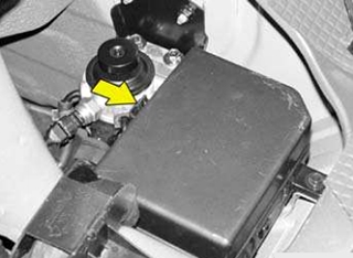
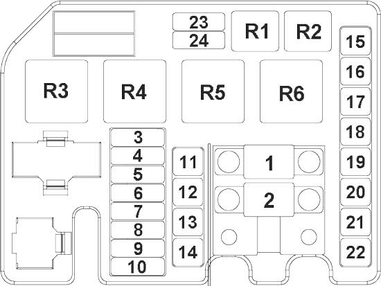
| № | A | Function/component |
|---|---|---|
| 1 | 80 | D4CB / D4BB & Euro 2: E/R Junction Box (RLY. 3). D4BB & Euro 1 : Glow Box |
| 2 | 120(D4CB) 100(D4BB) | Alternator (B+). I/P Fuse & Relay Box (Fuse - F7. F12. F14) |
| 3 | 10 | ECM |
| 4 | 10 | Alternator |
| 5 | 10 | Stop Lamp Switch. Stop Signal Relay |
| 6 | 10 | E/R Junction Box (RLY. 1) |
| 7 | 10 | E/R Junction BOX (RLY. 2) |
| 8 | 15 | - |
| 9 | 20 | D4CB: ECM |
| 10 | 10 | D4CB: ECM, Immobilizer Module |
| 11 | 50 | E/R Junction Box (RLY. 4), Ignition Switch |
| 12 | 30 | Engine Control Relay |
| 13 | 50 | E/R Junction Box (Fuse - F16. F17. F18. F19). I/P Fuse & Relay Box (Fuse - F29. F30, F31, Power Connector F3) |
| 14 | 40 | l/P Fuse & Relay Box (Fuse - F1, F16. Tail Lamp Relay) |
| 15 | 30 | E/R Junction Box (RLY. 6) |
| 16 | 30 | - |
| 17 | 40 | - |
| 18 | 30 | - |
| 19 | 40 | - |
| 20 | 30 | l/P Fuse & Relay Box (Blower Relay) |
| 21 | 40 | - |
| 22 | 30 | E/R Junction Box (RLY. 5) |
| 23 | 10 | D4CB: E/R Junction Box (RLY. 2, RLY. 6). Inlet Metering Valve, Stop Lamp Switch |
| 24 | 15 | D4CB: VGT Actuator, E/R Junction Box (RLY. 3) |
| R1 | A/C Relay | |
| R2 | Horn Relay | |
| R3 | Condenser Fan Relay | |
| R4 | Fuel Filter Heater Relay | |
| R5 | Start Relay | |
| R6 | Glow Relay | |
Advertisements
