Advertisements
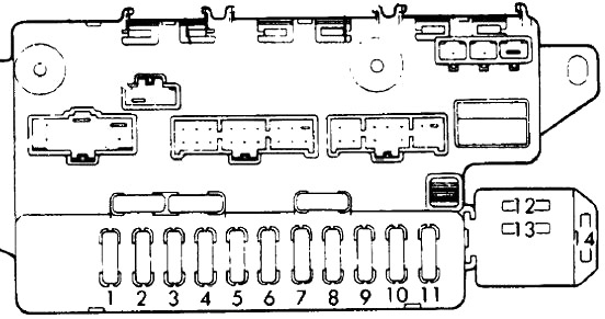
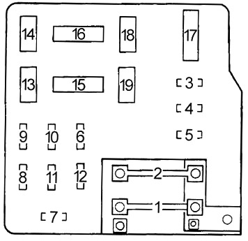
Fuse box diagram (fuse layout), location, and assignment of fuses and relays Honda Prelude (Mk3) (1987, 1988, 1989, 1990, 1991).

Checking and Replacing Fuses
Fuses and circuit breakers protect your vehicle’s electrical system from overloading. If electrical parts in your vehicle are not working, the system may have been overloaded and blown a fuse or tripped a circuit breaker. Before you replace or repair any electrical parts, check the appropriate fuses or circuit breakers.
To check a fuse, look at the silver-colored band inside the fuse. If the band is broken or melted, replace the fuse.
Notice
- Before replacing fuses check that the key has been removed from the ignition and that all the services are switched off and/or disengaged.
- Always replace a fuse with one that has the specified amperage rating. Using a fuse with a higher amperage rating can cause severe wire damage and could start a fire.
- Never replace a broken fuse with anything other than a new fuse.
- If a fuse blows again contact a qualified service center.
Passenger Compartment Fuse Box Diagram
The fuse panel is behind the cover below and to the left of the steering column.

| № | A | Protected Component |
|---|---|---|
| 1 | 7.5 | Warning Display, Starter (Manual Transmission), Neutral Safety Switch (Automatic Transmission), PGM-FI ECU, PGM-FI Main Relay, Control Box (PGM-CARB) |
| 2 | 10 | Stereo Radio Cassette Player, Cigarette Lighter Relay |
| 3 | 7.5 | Warning Display, Starter Solenoid, PGM-FI Electronic Control Unit, PGM-FI Main Relay |
| 4 | 15 | Power Door Lock Control Unit |
| 5 | 15 | Passenger's Power Window Switch |
| 6 | 15 | Power Window Control Unit, Driver's Power Window Switch |
| 7 | 20 | Automatic Seat Belt Retractors |
| 8 | 15 | Trunk Light, Dome & Ashtray Lights, Ignition Key Switch, Integrated Control Unit, Cigarette Lighter, Driver's Door Outer Handle Switch |
| 9 | 20 | Foglight Relay |
| 10 | 7.5 | Cruise Control Main Switch |
| 11 | 20 | Sun Roof Relay, Power Windows, Windshield Wipers, Integrated Control Unit, Combination Switch |
| 12 | 10 | Warning Display, Speed Sensor Amplifier, Automatic Transmission, Engine Controls |
| 13 | 10 | Integrated Control Unit, Back-Up Light Switch, Combination & Shift Position Console Switches, Seat Belt Beeper/Reminder Assembly, Gauge Assembly, Shift Lever Position & Safety Indicators, Clock |
| 14 | 30 | Sun Roof Motors |
| 15 | 15 | Combination Switch |
| 16 | 7.5 | Daytime Running Lights Relay |
| 17 | 15 | Power Mirrors, Condenser Fan Relay (PGM-CARB), Radiator Fan Relay, Cooling Fan Timer Unit (PGM-FI) |
| 18 | 10 | Rear Window Defogger, Heater Controls, A/C Controls |
Advertisements
Engine Compartment Fuse Box Diagram

| № | A | Protected Component |
|---|---|---|
| 19 | 70 | Power Distributor |
| 20 | 40 | Power Distributor (Ignition Switch) |
| 21 | 40 | Power Distributor (Ignition Switch) |
| 22 | 40 | Dash Fuse Box |
| 23 | 30 | Rear Window Defogger Relay |
| 24 | 40 | Power Window Relay, Dash Fuse Box |
| 25 | 40 | ALB Motor Relay |
| 26 | 15 | Antilock Brake Control Unit |
| 27 | 15 | Antilock Brake Control Unit |
| 28 | 15 | Antilock Brake Control Unit |
| 29 | 15 | Right Headlight Retractor Relay, Headlight Retractor Switch |
| 30 | 15 | Left Headlight Retractor Relay, Headlight Retractor & Combination Switches |
| 31 | 15 | Turn Signals/Hazard Relay, Hazard Switch |
| 32 | 20 | Horns, Brakelight Switch, Key Interlock Switch |
| 33 | 15 | Right Headlight |
| 34 | 15 | Left Headlight |
| 35 | 10 | PGM-FI Electronic Control Unit, Power Antenna, Cooling Fan Timer Unit, Radio Cassette Player, Automatic Transmission Control Unit, Stereo, Clock |
| 36 | 15 | Condenser Fan Relay |
| 37 | 10 | Alternator |
| 38 | 10 | PGM-CARB Control Unit, PGM-FI Main Relay |
| 39 | 20 | Radiator Fan Relay |
| R1 | - | |
| R2 | - | |
| R3 | Dimmer | |
| R4 | Lighting | |
| R5 | Condenser Fan | |
| R6 | - | |
| R7 | Radiator Fan | |
Advertisements
