
Advertisements
Fuse box diagram (fuse layout), location, and assignment of fuses and relays Honda Passport Mk2 (1997, 1998, 1999, 2000, 2001, 2002).
Checking and Replacing Fuses
Fuses and circuit breakers protect your vehicle’s electrical system from overloading. If electrical parts in your vehicle are not working, the system may have been overloaded and blown a fuse or tripped a circuit breaker. Before you replace or repair any electrical parts, check the appropriate fuses or circuit breakers.
To check a fuse, look at the silver-colored band inside the fuse. If the band is broken or melted, replace the fuse.
Notice
- Before replacing fuses check that the key has been removed from the ignition and that all the services are switched off and/or disengaged.
- Always replace a fuse with one that has the specified amperage rating. Using a fuse with a higher amperage rating can cause severe wire damage and could start a fire. If you do not have a replacement fuse with the proper rating for the circuit, install one with a lower rating.
- Never replace a broken fuse with anything other than a new fuse.
- If a fuse blows again contact a qualified service center.
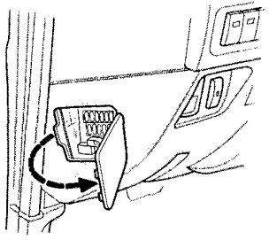
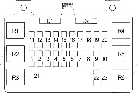
Passenger Compartment Fuse Box
The fuse block is behind the cover on the left side of the instrument panel.
| № | A | Protected Component |
|---|---|---|
| 1 | 20 | Accessory Power Sockets |
| 2 | 15 | Clock, Stereo Sound System |
| 3 | 10 | Starting System |
| 4 | 15 | Taillight Relay (A/T Gear Position Indicator, Alarm and Relay Controls, Dash and Console Lights, Fuel Injection System, Headlight Switch, Lights-on Reminder, Multiplex Control System, Parking Light, Tail Light, License Light, Power Door Locks/Keyless Entry/Security System, Trailer Lights Connector) |
| 5 | 10 | Alarm and Relay Controls, Cargo Light, Ceiling Light, Courtesy Lights, Dome Light Relay (2001), Ignition Key Reminder (LX), Map Light |
| 6 | 15 | ABS, Automatic Transmission Controls, Brake Lights, Cruise Control, Interlock System, Trailer Lighting Connector |
| 7 | 20 | Ignition Key Reminder (EX), Power Door Locks/Keyless Entry/Security System |
| 8 | 10 | Power Mirror Defoggers |
| 9 | 15 | Rear Window Defogger |
| 10 | 15 | Rear Window Defogger |
| 11 | 15 | ABS, Gauges, Indicators, Interlock System, Multiplex Control System |
| 12 | 15 | Automatic Transmission Controls, Fuel Injection System, Starting System |
| 13 | 15 | Ignition System |
| 14 | 15 | Automatic Transmission Controls, Back-up Lights, Cruise Control, Map Light Timer (2001), Multiplex Control System, Shift-on-the-fly System (2001-2002), Transmission Range Switch |
| 15 | 15 | Alarm and Relay Control Unit, Blower Controls, Power Moonroof, Power Windows, Shift-on-the-fly System (2000), Trailer Lighting Connector, Turn Signal Lights |
| 16 | 10 | Alarm and Relay Control Unit, Rear Window and Mirror Defoggers, Rear Wiper/Washer |
| 17 | 20 | Alarm and Relay Control Unit, Windshield Wiper/Washer |
| 18 | 10 | Power Mirrors, Stereo Sound System |
| 19 | 15 | Accessory Power Sockets, Cigarette Lighter |
| 20 | 10 | Security and Keyless Entry System |
| 21 | 30 | Power Moonroof, Power Seat (2001-2002), Power Windows |
| 22 | 10 | SRS |
| 23 | - | - |
| R1 | Taillight | |
| R2 | - | |
| R3 | Accessory Power Socket | |
| R4 | Power Window | |
| R5 | 2001: Dome Light | |
| R6 | Rear Window Defogger | |
| D1 | Ceiling Lights, Keyless Entry and Security System | |
| D2 | Keyless Entry and Security System | |
Advertisements
Engine Compartment Fuse Box
It is on the right side of the engine compartment.
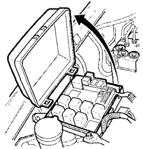
Diagram (Type 1)

| № | A | Protected Component |
|---|---|---|
| 1 | 15 | Hazard Warning Lights, Trailer Lighting Connector |
| 2 | 10 | Alarm and Relay Control Unit, Data Link Connector (DLC), Security Horn |
| 3 | 10 | Alternator |
| 4 | - | - |
| 5 | 15 | Blower Controls |
| 6 | 15 | Blower Controls |
| 7 | 10 | Air Delivery |
| 8 | 10 | Left Headlights, Fog Lights |
| 9 | 10 | Right Headlight |
| 10 | 15 | Fog Lights |
| 11 | 20 | Heated Oxygen Sensors |
| 12 | 20 | Fuel Pump |
| 13 | 15 | Automatic Transmission Controls, Fuel Injection System, Gauges |
| 14 | Daytime Running Lights | |
| 15 | 60 | Fuel Injection System, Power Distribution (BAT) |
| 16 | 100 | A/C Compressor Controls, Blower Controls, Charging System, Fog Lights, Power Distribution (BAT), Starting System |
| 17 | 30 | Engine Control Module |
| 18 | 50 | ABS |
| 19 | 50 | Power Distribution (BAT) |
| 20 | 30 | Condenser Fan |
| R1 | Fuel Pump | |
| R2 | - | |
| R3 | Headlight | |
| R4 | Starter | |
| R5 | Condenser Fan | |
| R6 | - | |
| R7 | - | |
| R8 | A/C Thermo | |
| R9 | Engine Control Module (ECM) (M/T) | |
| Powertrain Control Module (PCM) (A/T) | ||
| R10 | - | |
| R11 | Fog Light | |
| R12 | Heater-A/C | |
| R13 | A/C Compressor | |
| D1 | Brake System Indicator Light | |
Advertisements
Diagram (Type 2)
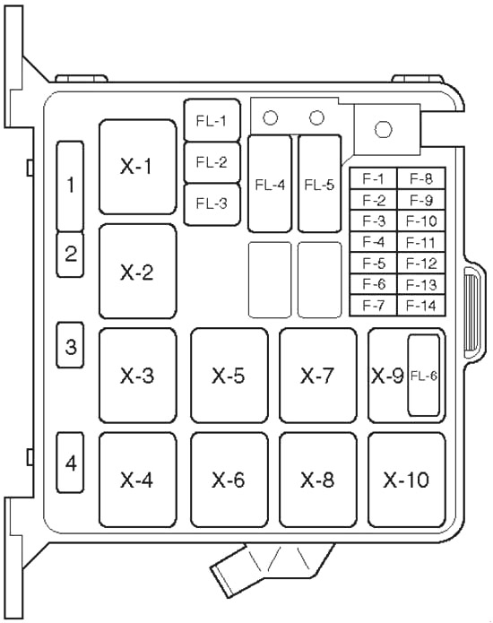
| № | A | Protected Circuits |
|---|---|---|
| F1 | 15 | Hazard warning light |
| F2 | 10 | Alarm & relay control unit, Horn, Anti - theft horn |
| F4 | 20 | Blower motor, Blower resistor |
| F5 | 10 | A/C thermostat relay, Electronic thermostat, A/C compressor relay, Magnetic clutch |
| F8 | 10 | Headlight - LH, High beam indicator light, Fog light relay |
| F9 | 10 | Headlight - RH |
| F10 | 15 | Fog light |
| F11 | 20 | Oxygen sensor |
| F12 | 20 | Fuel pump |
| F13 | 15 | Engine control module |
| F14 | - | - |
| FL1 | 60 | EHCU |
| FL2 | 30 | Condenser fan unit |
| FL4 | 100 | Ignition switch, starter relay, A/C, generator, heater relay, Fuse: F10, FL1, FL2, FL5, FL6 |
| FL5 | 60 | Ignition switch, fuel pump relay, engine control module relay, power train module |
| FL6 | - | - |
| X1 | Headlight | |
| X2 | Fog light | |
| X3 | Starter | |
| X4 | A/C compressor | |
| X5 | Thermo | |
| X6 | Heater | |
| X7 | Fuel pump | |
| X8 | Engine control module | |
| X9 | 6VD1: Condenser fan | |
| X10 | - | |
| 1 | Brake | |
| 2 | - | |
| 3 | - | |
| 4 | - | |
Advertisements