
Advertisements
Fuse box diagram (fuse layout), location, and assignment of fuses and relays Honda Odyssey Mk4 (RL5) (2011, 2012, 2013, 2014, 2015, 2016, 2017).

Checking and Replacing Fuses
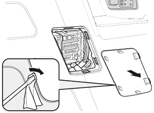
If something electrical in your vehicle stops working, the first thing you should check for is a blown fuse. Determine from the chart, or the diagram on the fuse box lid, which fuse or fuses control that device. The diagram for the interior driver’s side fuse box is on the kick panel below the fuse box. Check those fuses first, but check all the fuses before deciding that a blown fuse is the cause. Replace any blown fuses, and check if the device works.
- Turn the ignition switch to LOCK (0). Turn headlights and all accessories off.
- Remove the fuse box cover.
- Check the large fuse in the engine compartment. If the fuse is blown, use a Phillips-head screwdriver to remove the screw and replace it with a new one.
- Inspect the small fuses in the engine compartment and the vehicle interior. If there is a burned out fuse, remove it with the fuse puller and replace it with a new one.
- Look for a burned wire inside the fuse. If it is burned, replace it with one of the spare fuses of the same rating or lower.
If you cannot drive the car without fixing the problem, and you do not have a spare fuse, take a fuse of the same rating or a lower rating from one of the other circuits. Make sure you can do without that circuit temporarily (such as the accessory socket or radio).
If you replace the blown fuse with a spare fuse that has a lower rating, it might blow out again. This does not indicate anything wrong. Replace the fuse with one of the correct rating as soon as you can. - If the replacement fuse of the same rating blows in a short time, there is probably a serious electrical problem in your car. Leave the blown fuse in that circuit and have your car checked by a qualified technician.
Notice
- Replacing a fuse with one that has a higher rating greatly increases the chances of damaging the electrical system. If you do not have a replacement fuse with the proper rating for the circuit, install one with a lower rating.
- Never replace a broken fuse with anything other than a new fuse.
Passenger Compartment
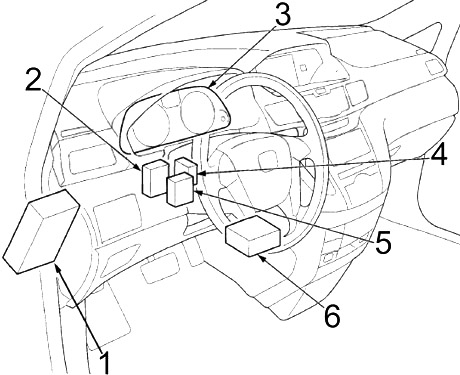
- Fuse Box №1
- Tire Pressure Monitoring System (TPMS) Control Unit
- Gauge Control Module
- Headlight Leveling Control Unit (with HID)
- Parking and Back-Up Sensor Control Unit
- Supplemental Restraint System (SRS) Unit
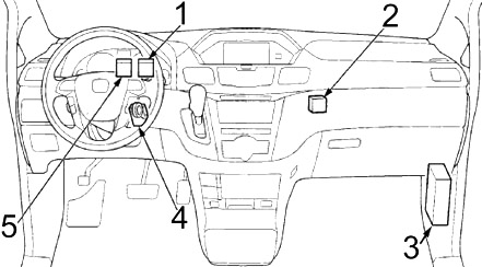
- Driver’s Junction Box №1
- Center Junction Box
- Fuse Box №2
- Immobilizer-Keyless Control Unit
- Driver’s Junction Box №2
Advertisements
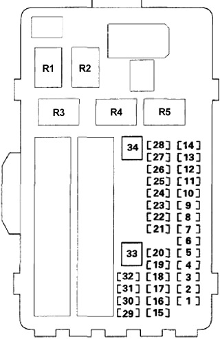
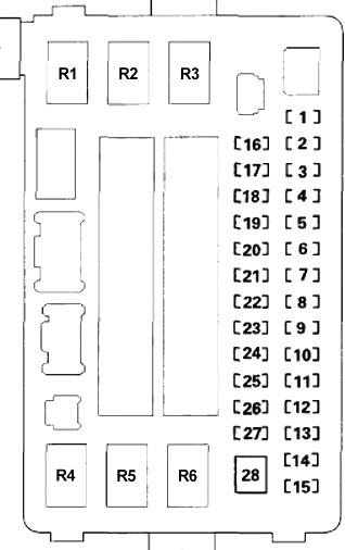
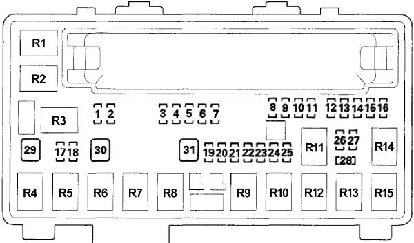
Passenger Compartment Fuse Box №1
Located under the dashboard. Fuse locations are shown on the label on the side panel.

| № | A | Protected Component |
|---|---|---|
| 1 | 7.5 | Front Passenger's Door Lock Actuator |
| 2 | 7.5 | Right Sliding Door Lock Actuator |
| 3 | 7.5 | Driver's Door Lock Actuator |
| 4 | 7.5 | Front Passenger's Door Lock Actuator |
| 5 | 7.5 | Right Sliding Door Lock Actuator |
| 6 | 7.5 | Driver's Door Lock Actuator (Power Door Lock Relay (DR UNLOCK)), Power Door Lock Relay (DR UNLOCK) |
| 7 | 20 | Fuses (Passenger Compartment Fuse Box №1): № 1, 2, 3, 4, 5 |
| 8 | 10 | HAC Option |
| 9 | 20 | Left Power Sliding Door Control Unit |
| 10 | 15 | Fuses (Luggage Compartment Fuse Box): №12, 13 |
| 11 | 7.5 | Reverse Relay, Automatic Dimming Inside Mirror, Electrical Compass, Gauge Control Module, Back-Up Lights, Multiplex Integrated Control Unit (MICU), Parking and Back-Up Sensor Control Unit, Power Mirror Control Unit, Power Seat Control Unit, Shift Lock Solenoid, Tire Pressure Monitoring System (TPMS) Control Unit |
| 12 | 20 | Fuses (Engine Compartment Fuse Box №1): № 3, 4, 5, 6, 7 |
| 13 | 7.5 | Audio Display-USB Adapter Control Unit, Audio Unit, Audio-Navigation Unit, Cargo Area Accessory Power Socket Relay, Front Lower Accessory Power Socket Relay, Front Upper Accessory Power Socket Relay, Front Active Noise Cancellation (ANC) Microphone, Front HFL-ANC Microphone, Navigation Display Unit, Interface Dial, Key Interlock Solenoid, Rear Active Noise Cancellation (ANC) Microphone |
| 14 | 7.5 | Powertrain Control Module - PCM, Starter Signal |
| 15 | 20 | Driver's Power Seat Front Up-Down Motor (Driver's Power Seat Adjustment Switch), Driver's Power Seat Slide Motor (Driver's Power Seat Adjustment Switch), HandsFreeLink Control Unit, Power Seat Control Unit |
| 16 | 20 | Moonroof Control Unit/Motor |
| 17 | 20 | Left Rear Power Window Relay, Left Rear Power Window Switch |
| 18 | 10 | Smart Entry System |
| 19 | 20 | Power Window Master Switch |
| 20 | - | - |
| 21 | 20 | Fuel Pump (PGM-FI Main Relay №2), Immobilizer-Keyless Control Unit, Powertrain Control Module - PCM (IG1) |
| 22 | 15 | Fuses (Passenger Compartment Fuse Box №1): № 19, 20, 21, 22, 23 |
| 23 | 7.5 | VSA Modulator-Control Unit, Yaw Rate Acceleration Sensor |
| 24 | 7.5 | Electrical Load Detector (ELD), Brake Pedal Position Switch, Powertrain Control Module (PCM) |
| 25 | 7.5 | Powertrain Control Module - PCM (STRLD) |
| 26 | 7.5 | A/C Compressor Clutch Relay, A/C Condenser Fan Relay (A/C Diode A), AC Inverter Unit, Automatic Dimming Inside Mirror, Climate Control Unit, Cool Box Motor, Fan Control Relay (A/C Diode A), Front Blower Motor Relay, HVAC Control Unit, Power Mirror Control Unit, Power Window Master Switch, Rear A/C Control Panel, Rear A/C Control Unit, Rear Blower Motor Relay, Rear Window Defogger Relay, Seat Heater Relay |
| 27 | 7.5 | Daytime Running Lights (DRL), Relay Control Module |
| 28 | 7.5 | Key Lock |
| 29 | 7.5 | Driver's Lumbar Support Motor (Driver's Lumbar Support Switch) |
| 30 | 7.5 | Tire Pressure Monitoring System (TPMS) Control Unit |
| 31 | - | - |
| 32 | 20 | Driver's Power Seat Rear Up-Down Motor, Driver's Power Seat Adjustment Switch, Driver's Power Seat Recline Motor, Power Seat Control Unit |
| 33 | 40 | Left Power Sliding Door Control Unit |
| 34 | - | - |
| R1 | Starter Cut №1 | |
| R2 | Starter Cut №2 | |
| R3 | PGM-FI Main №2 (Fuel Pump) | |
| R4 | Ignition (IG2 Cut) | |
| R5 | Ignition (ACC Cut) | |
Advertisements
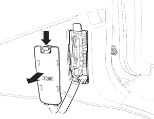
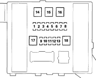
Passenger Compartment Fuse Box №2
Located on the lower side panel. Take off the cover to open.
| № | A | Protected Component |
|---|---|---|
| 1 | 30 | Audio Amplifier |
| 2 | 20 | Right Rear Power Window Relay, Right Rear Power Window Switch |
| 3 | 10 | Engine Mount Control Unit (Active Control Engine Mount (ACM) Control Relay) |
| 4 | - | - |
| 5 | 20 | Seat Heater Control Unit (Seat Heater Relay) |
| 6 | - | - |
| 7 | 20 | Front Passenger's Power Seat Slide Motor (Front Passenger's Power Seat Adjustment Switch) |
| 8 | 20 | Front Passenger's Power Seat Recline Motor (Front Passenger's Power Seat Adjustment Switch) |
| 9 | - | - |
| 10 | - | - |
| 11 | - | - |
| 12 | - | - |
| 13 | 20 | Right Power Sliding Door Control Unit |
| 14 | 15 | Cargo Area Accessory Power Socket (Cargo Area Accessory Power Socket Relay) |
| 15 | 15 | Front Lower Accessory Power Socket (Front Console Power Socket Relay) |
| 16 | - | - |
| 17 | - | - |
| 18 | 20 | Front Passenger's Power Window Switch |
| 19 | 10 | Supplemental Restraint System (SRS) Unit |
| 20 | 7.5 | Active Control Engine Mount (ACM) Control Relay, Engine Mount Control Unit, Right Power Sliding Door Control Unit, Seat Heater Control Unit |
| 21 | 7.5 | Headlight Leveling Control Unit (with HID) |
| 22 | - | - |
| 23 | 7.5 | Front Passenger's Airbag Cutoff Indicator, Occupant Detection System (ODS) Unit, Supplemental Restraint System (SRS) Unit, Fuse (Passenger Compartment Fuse Box №1): № 24 |
| 24 | - | - |
| 25 | 7.5 | Illumination: A/T Gear Position Indicator Panel Light, Audio Unit, Audio Display Unit, BSI OFF Switch Light, Climate Control Unit, Cool Box Switch Light, Driver's Footwell Light, Driver's Power Tailgate Switch Light, Glove Box Light, Hazard Warning Switch Light, HVAC Control Unit, HomeLink Unit, Interior Light Switch Light, Left B-pillar Power Sliding Door Switch, Parking And Back-Up Sensor Switch Light, Passenger's Footwell Light, Power Sliding Door Switch Light, Rear A/C Control Panel, Rear Controller and Screen, Res Auxiliary Jack Assembly, Right B-pillar Power Sliding Door Switch, Steering Wheel Switches Lights, VSA OFF Switch Light |
| 26 | - | - |
| 27 | 15 | Front Upper Accessory Power Socket (Front Upper Accessory Power Socket Relay) |
| 28 | - | - |
| R1 | Seat Heater | |
| R2 | Right Rear Power Window | |
| R3 | Active Control Engine Mount (ACM) Control | |
| R4 | Cargo Area Accessory Power Socket | |
| R5 | Front Lower Accessory Power Socket | |
| R6 | Front Upper Accessory Power Socket | |
Passenger Compartment Relay Box
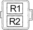
| № | Relay |
|---|---|
| R1 | Interior Lights Cut |
| R2 | Front Blower Motor |
Engine Compartment
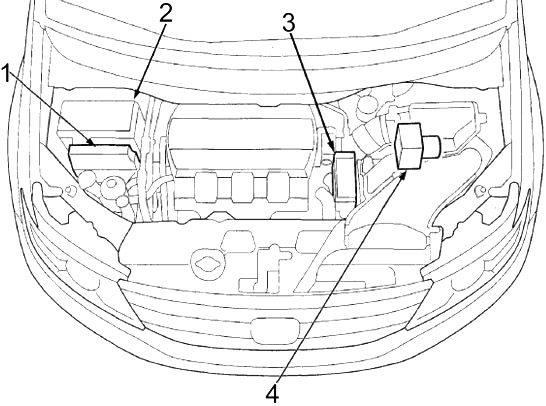
- Powertrain Control Module (PCM)
- Fuse Box №1
- Fuse Box №2
- VSA Modulator-Control Unit
Advertisements
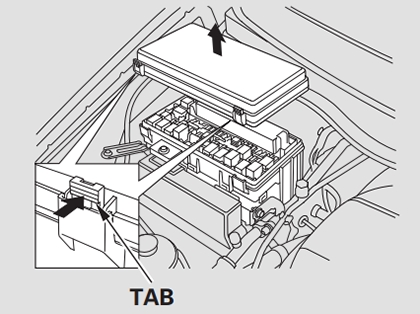
Fuse Box №1 Diagram
Located on the passenger’s side, near the windshield washer reservoir. Push the tabs to open the box.
| № | A | Protected Component |
|---|---|---|
| 1 | - | - |
| 2 | - | - |
| 3 | 15 | Alternator, Evaporative Emission Control (EVAP) Canister Purge Valve, PCM (VBSOL) |
| 4 | 15 | Rear Window Washer Motor Relay, Wiper Main Relay, Windshield Washer Motor Relay, Windshield/Rear Window Washer Motor (Windshield Washer Motor Relay or Rear Window Washer Motor Relay) |
| 5 | 7.5 | Powertrain Control Module - PCM (VBSOL2) |
| 6 | 7.5 | Relay Control Module (IG1 ECU FR) |
| 7 | - | - |
| 8 | 15 | PGM-FI Sub Relay, Front Air Fuel Ratio (A/F) Sensor, Front Secondary Heated Oxygen Sensor (HO2S), Rear Air Fuel Ratio (A/F) Sensor, Rear Secondary Heated Oxygen Sensor (HO2S) |
| 9 | 15 | Electronic Throttle Control System (ETCS) Control Relay, Powertrain Control Module - PCM (IG1 ETCS) |
| 10 | 15 | PGM-FI Main Relay №1, PGM-FI Main Relay №2, Powertrain Control Module - PCM (IGP), Crankshaft Position (CKP) Sensor, Camshaft Position (CMP) Sensor, Electronic Throttle Control System (ETCS) Control Relay, Injectors, Mass Airflow (MAF) Sensor, Fuse (Engine Compartment Fuse Box №1): № 28 |
| 11 | 15 | Ignition Coil Relay, Ignition Coils |
| 12 | - | - |
| 13 | 7.5 | Powertrain Control Module - PCM (VBUM) |
| 14 | - | - |
| 15 | 20 | Active Noise Cancellation (ANC) Unit, Audio Display-USB Adapter Control Unit, Audio-Navigation Unit, Audio Unit, HandsFreeLink Control Unit, Navigation Display Uni |
| 16 | 10 | Audio Display Unit, Climate Control Unit, Data Link Connector (DLC), Multiplex Integrated Control Unit (MICU), Front HFL-ANC Microphone, Gauge Control Module, HomeLink Unit, Immobilizer-Keyless Control Unit, Left Power Sliding Door Control Unit, Power Mirror Control Unit, Power Seat Control Unit, Power Tailgate Control Unit, Power Window Master Switch, Rear Controller and Screen, Rear MICU, Relay Control Module, Right Power Sliding Door Control Unit |
| 17 | 7.5 | A/C Compressor Clutch (A/C Compressor Clutch Relay) |
| 18 | 20 | Fog Light Relay, Left/Right Fog Light |
| 19 | - | - |
| 20 | 10 | Right Headlight High Beam, Relay Control Module |
| 21 | - | - |
| 22 | 10 | Taillight Relay, Left Front Parking/Side Marker Light, Left Inner Taillight, Left License Plate Light, Left Rear Side Marker/Taillight, Right Front Parking/Side Marker Light, Right Inner Taillight, Right License Plate Light, Right Taillight, Fuses (Passenger Compartment Fuse Box №2): № 25 |
| 23 | - | - |
| 24 | 10 | Left Headlight High Beam, Relay Control Module |
| 25 | - | - |
| 26 | 15 | Right Headlight (Low Beam) or Right HID Unit |
| 27 | 15 | Left Headlight (Low Beam) or Left HID Unit |
| 28 | 7.5 | PGM-FI Subrelay, Radiator Fan Relay (A/C Diode B) |
| 29 | 30 | A/C Condenser Fan Motor (Radiator Fan Relay, Fan Control Relay), Radiator Fan Motor (Radiator Fan Relay) |
| 30 | 30 | A/C Condenser Fan Motor (A/C Condenser Fan Relay) |
| 31 | 30 | Windshield Wiper High/Low Relay (Wiper Main Relay), Windshield Wiper Motor (Wiper Main Relay, Windshield Wiper Motor Relay, and Windshield Wiper High/Low Relay), Windshield Wiper Motor Relay (Wiper Main Relay) |
| R1 | Rear Windoow Defogger | |
| R2 | A/C Compressor | |
| R3 | Ignition Coil | |
| R4 | Radiator Fan | |
| R5 | Electronic Throttle Control System (ETCS) Control | |
| R6 | A/C Condenser Fan | |
| R7 | Wiper Main | |
| R8 | Fog Light | |
| R9 | PGM-FI Sub | |
| R10 | PGM-FI Main №1 | |
| R11 | Headlight Low | |
| R12 | Fan Control | |
| R13 | Horn | |
| R14 | Taillight | |
| R15 | Rear Blower Motor | |
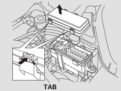
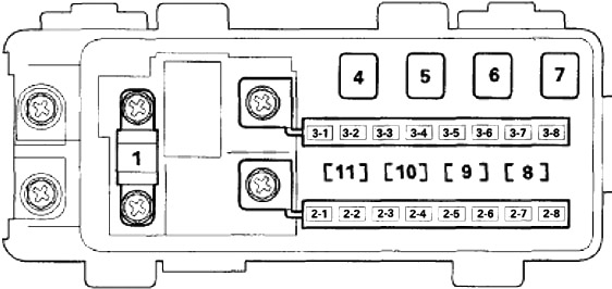
Fuse Box №2 Diagram
The secondary under-hood fuse box is near the battery. Push the tabs to open the box.
| № | A | Protected Component |
|---|---|---|
| 1 | 125 | Alternator, Battery, Power Supply |
| 2-1 | 60 | Fuses (Engine Compartment Fuse Box №1): № 17, 18, 29, 30 |
| 2-2 | 50 | Fuses (Passenger Compartment Fuse Box №2): № 12, 13, 14, 15, 26, 27, 28 |
| 2-3 | 30 | Rear Blower Motor (Rear Blower Motor Relay) |
| 60 | HondaVAC | |
| 2-4 | 30 | Fuse (Engine Compartment Fuse Box №2): № 11, Fuses (Engine Compartment Fuse Box №1): № 8, 9, 10, 11, 12, 13, 14, 15, 16 |
| 2-5 | 40 | VSA Modulator-Control Unit |
| 2-6 | 30 | Fuses (Engine Compartment Fuse Box №1): № 9, 10 |
| 2-7 | 30 | VSA Modulator-Control Unit |
| 2-8 | 30 | Fuses (Engine Compartment Fuse Box №1): № 8 |
| 3-1 | 50 | Fuses (Passenger Compartment Fuse Box №2): № 6, 7, 8, 9, 20, 33 |
| 3-2 | 50 | Ignition Switch, Starter (Starter Cut Relay №1 and Starter Cutrelay №2), Fuse (Passenger Compartment Fuse Box №2): № 25 |
| 3-3 | 60 | Fuses (Luggage Compartment Fuse Box): № 1, 8, 14, 15, 16 |
| 3-4 | 50 | Fuses (Passenger Compartment Fuse Box №2): № 1, 2, 3, 4, 5, 6, 7, 8, 9, 10, 11, 18 fuse/relay box |
| 3-5 | 50 | Fuses (Passenger Compartment Fuse Box №1): № 15, 16, 17, 18, 19, 29, 30, 31, 32 |
| 3-6 | 60 | Headlight Low Relay, Fuses (Engine Compartment Fuse Box №1): № 19, 20, 21, 22, 23, 24, 25, 26, 27, 31 |
| 3-7 | 40 | Front Blower Motor (Front Blower Motor Relay) |
| 3-8 | 40 | Right Power Sliding Door Control Unit |
| 4 | - | - |
| 5 | 40 | - |
| 6 | 40 | Rear Window Defogger (Rear Window Defogger Relay) |
| 7 | - | - |
| 8 | 7.5 | Battery Sensor |
| 9 | 20 | Brake Pedal Position Switch, Brake Lights, Multiplex Integrated Control Unit (MICU), High Mount Brake Light, Horn |
| Relay, Horns | ||
| 10 | 15 | Hazard Warning Switch, Multiplex Integrated Control Unit (MICU) |
| 11_ | 7.5 | Interior Lights Cut Relay, Cargo Area Light, Driver's Door Courtesy Light, Driver's Vanity Mirror Light, Front Individual Map Lights, Front Passenger's Door Courtesy Light, Ignition Key Light, Interior Lights Cut Relay, Left Rear Individual Map Light (2nd), Left Rear Individual Map Light (3rd), Passenger's Vanity Mirror Light, Power Tailgate Inside Switch, Right Rear Individual Map Light (2nd), Right Rear Individual Map Light (3rd) |
Advertisements
Luggage Compartment Fuse Box
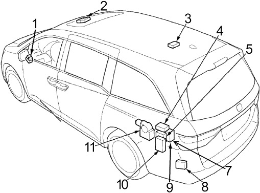
- Relay Box
- Moonroof Control Unit/Motor
- Electrical Compass Unit
- Blind Spot Information (BSI) Control Unit
- AC Inverter Unit
- –
- Fuse Box
- Left Blind Spot Information (BSI) Radar Unit
- Rear MICU
- Power Tailgate Control Unit
- Left Power Sliding Door Control Unit
The rear fuse box is located on the left side of the cargo area. Remove the cover by prying on the edge of the cover using a flat-tip screwdriver.
| № | A | Protected Component |
|---|---|---|
| 1 | 20 | Power Tailgate Control Unit |
| 2 | - | - |
| 3 | - | - |
| 4 | 10 | Tailgate Release Actuator, Tailgate Release Actuator Relay |
| 5 | 7.5 | Left Sliding Door Lock Actuator, Left Sliding Door Lock Actuator, Power Door Lock Relay (LOCK), Power |
| Door Lock Relay (UNLOCK) | ||
| 6 | - | - |
| 7 | - | - |
| 8 | - | - |
| 9 | - | - |
| 10 | - | - |
| 11 | - | - |
| 12 | 10 | Rear Window Wiper Motor, Rear Window Wiper Motor Relay |
| 13 | 7.5 | Blind Spot Information (BSI) Control Unit, Left Power Sliding Door Control Unit, Power Tailgate Control Unit, Rear Multiplex Integrated Control Unit (MICU) |
| 14 | 40 | Power Tailgate Control Unit |
| 15 | 30 | AC Inverter Unit |
| 16 | - | - |
| 17 | - | - |
| 18 | - | - |
Advertisements