
Advertisements
Fuse box diagram (fuse layout), location, and assignment of fuses and relays Honda Insight (ZE2/ZE3) (2010, 2011, 2012, 2013, 2014).

Checking and Replacing Fuses
If something electrical in your vehicle stops working, the first thing you should check for is a blown fuse. Determine from the chart, or the diagram on the fuse box lid, which fuse or fuses control that device. Check those fuses first, but check all the fuses before deciding that a blown fuse is the cause. Replace any blown fuses, and check if the device works.
- Turn the ignition switch to LOCK (0). Make sure the headlights and all other accessories are off.
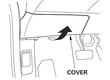
- Remove the cover from the fuse box.
- Check each of the large fuses in the under-hood fuse box on the 12-volt battery by looking through the top at the wire inside. Replacement of these fuses should be done by your dealer.
- Check the smaller fuses in the under-hood fuse boxes and all the fuses in the interior fuse box by pulling out each one with the fuse puller provided in the interior fuse box.
- Look for a blown wire inside the fuse. If it is blown, replace the fuse with one of the spare fuses of the same rating or lower.
If you cannot drive the car without fixing the problem, and you do not have a spare fuse, take a fuse of the same rating or a lower rating from one of the other circuits. Make sure you can do without that circuit temporarily (such as the accessory socket or radio).
If you replace the blown fuse with a spare fuse that has a lower rating, it might blow out again. This does not indicate anything wrong. Replace the fuse with one of the correct rating as soon as you can. - If the replacement fuse of the same rating blows in a short time, there is probably a serious electrical problem in your car. Leave the blown fuse in that circuit and have your car checked by a qualified technician.
Notice
- Replacing a fuse with one that has a higher rating greatly increases the chances of damaging the electrical system. If you do not have a replacement fuse with the proper rating for the circuit, install one with a lower rating.
- Never replace a broken fuse with anything other than a new fuse.
Passenger Compartment
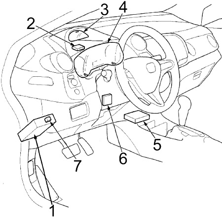
- Fuse Box
- Tire Pressure Monitoring System (TPMS) Control Unit
- Gauge Control Module
- Gauge Control Module
- Supplemental Restraint System (SRS) Unit
- Electronic Power Steering(EPS) Control Unit
- Hatch Release Actuator Relay
Instrument Panel Fuse Box Diagram
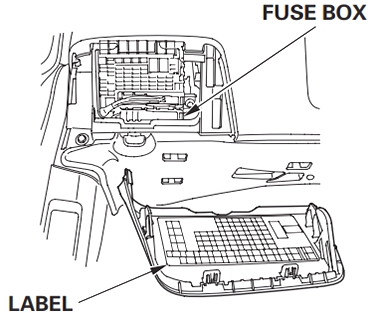
The interior fuse box is behind the dashboard on the driver’s side. The label is attached to the backside of the cover. To see the interior fuse box label, remove the cover by pulling it toward you while holding the bottom center part of the cover.
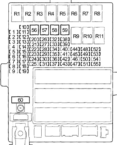
| № | A | Protected Component |
|---|---|---|
| 1 | 15 | Audio-Navigation Unit (With Navigation), Audio Unit (Without Navigation), Cargo Area Light, Ceiling Light, Data Link Connector (DLC), Gauge Control Module, Immobilizer-Keyless Control Unit, HandsFreeLink Control Unit, Individual Map Light, Multiplex Integrated Control Unit (MICU) (+B BACK UP), Motor Control Module (MCM) |
| 2 | 7.5 | Tire Pressure Monitoring System (TPMS) Control Unit |
| 3 | 20 | Power Window Master Switch |
| 4 | - | - |
| 5 | 10 | Back-up Light, Multiplex Integrated Control Unit (MICU) |
| 6 | 10 | Supplemental Restraint System (SRS) Unit |
| 7 | 10 | Powertrain Control Module - PCM (VBSOL) |
| 8 | 7.5 | Occupant Detection System (ODS) Unit, Front Passenger's Airbag Cutoff Indicator, Supplemental Restraint System (SRS) Unit |
| 9 | - | - |
| 10 | 7.5 | A/C Compressor Clutch Relay, Blower Motor Relay, Climate Control Unit, Fan Control Relay (A/C Diode A), Optional Connector, Power Mirror Switch, Radiator Fan Relay (A/C Diode A), Rear Window Defogger Relay, Recirculation Control Motor |
| 11 | 7.5 | EPS Control Unit (IG1), VSA Modulator-control Unit (IG1), Yaw Rateacceleration Sensor (With VSA), ABS Modulator-Control Unit (MTR) (Without VSA) |
| 12 | 10 | DC-DC Converter, Evaporative Emission Control (EVAP) Canister Purge Valve, Powertrain Control Module - (Idle Stop Switch), Mass Air Flow (MAF) Sensor, Secondary Heated Oxygen Sensor (HO2S) |
| 13 | 20 | Accessory Power Socket |
| 14 | 7.5 | Audio-Navigation Unit (With Navigation), Audio Unit (Without Navigation), Key Interlock Solenoid, HandsFreeLink Control Unit, MICU (ACC), Optional Connector |
| 15 | 7.5 | Daytime Running Light, Multiplex Integrated Control Unit (MICU) |
| 16 | 10 | Rear Window Wiper Motor |
| 17 | 20 | Front Passenger's Power Window Motor, Front Passenger's Power Window Switch Light |
| 18 | 20 | Right Rear Power Window Motor, Power Window Master Switch, Right Rear Power Window Switch Light |
| 19 | 20 | Left Rear Power Window Motor, Power Window Master Switch, Left Rear Power Window Switch Light |
| 20 | 15 | Fuel Pump (PGM-FI Main Relay №2 (2012-2014)), Immobilizer-Keyless Control Unit, Powertrain Control Module - PCM (IG1) (2012-2014) |
| 21 | 15 | Washer Motor, Multiplex Integrated Control Unit (MICU) |
| 22 | 7.5 | Electrical Load Detector (ELD), Gauge Control Module, Multiplex Integrated Control Unit - MICU (IG1 METER), Motor Control Module (MCM), Shift Lock Solenoid, Tire Pressure Monitoring System (TPMS) Control Unit |
| 23 | 10 | Turn Signal/Hazard Relay, Multiplex Integrated Control Unit (MICU) |
| 24 | 10 | Brake Pedal Position Switch, High Mount Brake Light, Left Brake Light, Right Brake Light, Horn Relay, Multiplex Integrated Control Unit (MICU), Powertrain Control Module (PCM) |
| 25 | - | - |
| 26 | 10 | Air Fuel Ratio (A/F) Sensor, Evaporative Emission Control (EVAP) Canister Vent Shut Valve, Fuse: № 31 (7.5 A) |
| 27 | 30 | Power Door Lock, Multiplex Integrated Control Unit (MICU) |
| 28 | 20 | Headlamp (Main), Multiplex Integrated Control Unit (MICU) |
| 29 | 10 | Parking Light, Multiplex Integrated Control Unit (MICU) |
| 30 | 30 | Radiator Fan Motor (Radiator Fan Relay), A/C Condenser Fan Motor (Fan Control Relay) (2012-2014) |
| 31 | 7.5 | A/C Condenser Fan Relay (A/C Diode B) |
| 32 | 10 | Right Headlight (Low Beam) |
| 33 | 20 | Ignition Coil Relay, Fuses (Engine Compartment): №1 (15 A), 2 (15 A) |
| 34 | 10 | Left Headlight (Low Beam) |
| 35 | 15 | Front Passenger's Door Lock Actuator, Right Rear Door Lock Actuator |
| 36 | 15 | Driver's Door Lock Actuator, Left Rear Door Lock Actuator |
| 37 | 30 | ABS Modulator-Control Unit (Without VSA), VSA Modulator-Control Unit |
| 38 | 15 | Driver's Door Lock Actuator |
| 39 | 15 | Crankshaft Position (CKP) Sensor, Camshaft Position (CMP) Sensor, Electronic Throttle Control System (ETCS) Control Relay, Injectors, Powertrain Control Module - PCM (IGP), PGM-FI Main Relay №1, PGM-FI Main Relay №2 (Fuel Pump) |
| 40 | - | - |
| 41 | - | - |
| 42 | 10 | Motor Control Module (MCM), MCM Relay №1, MCM Relay №2 |
| 43 | 7.5 | A/C Compressor (A/C Compressor Clutch Relay) |
| 44 | 7.5 | Starter Cut Relay, Powertrain Control Module - PCM (STS) |
| 45 | 7.5 | Hatch Release Actuator Relay, Hatch Release Actuator |
| 46 | - | - |
| 47 | 30 | A/C Condenser Fan Motor (A/C Condenser Fan Relay), Radiator Fan Motor (Fan Control Relay) (2010-2011) |
| 48 | 10 | Left Headlight (High Beam) |
| 49 | 15 | Front Passenger's Door Lock Actuator, Right Rear Door Lock Actuator |
| 50 | 15 | Left Rear Door Lock Actuator |
| 51 | 10 | Right Headlight (High Beam) |
| 52 | 15 | Electronic Throttle Control System (ETCS) Control Relay, Powertrain Control Module - PCM (IG1ETCS) |
| 53 | 10 | Intelligent Power Unit (IPU) Module Fan (Motor Control Module (MCM) Relay №2), Motor Power Inverter (MPI) Module (Motor Control Module (MCM) Relay №2) |
| 54 | - | - |
| 55 | 10 | Left Power Mirror Defogger, Right Power Mirror Defogger |
| 56 | 30 | Front Wiper, Multiplex Integrated Control Unit (MICU) |
| 57 | 30 | Blower Motor (Blower Motor Relay) |
| 58 | 30 | ABS Modulator-Control Unit (Without VSA), VSA Modulator-Control Unit |
| 59 | 30 | Without Power Mirror Defogger: Rear Window Defogger Relay (Lower Rear Window Defogger, Upper Rear Window Defogger, Noise Reduction Condenser) |
| 40 | With Power Mirror Defogger: Rear Window Defogger Relay (Lower Rear Window Defogger, Upper Rear Window Defogger, Noise Reduction Condenser, Fuse: №55 (10 A)) | |
| 60 | 50 | Ignition switch |
| 30 | Headlamp Washer | |
| R1 | Power Window | |
| R2 | Blower Motor | |
| R3 | Air Fuel Ratio (A/F) Sensor | |
| R4 | Lighting | |
| R5 | Ignition Coil | |
| R6 | PGM-FI Main №1 | |
| R7 | Electronic Throttle Control System (ETCS) Control | |
| R8 | Rear Window Defogger | |
| R9 | Driver's Door Unlock | |
| R10 | Starter Cut | |
| R11 | - | |
Advertisements
Engine Compartment
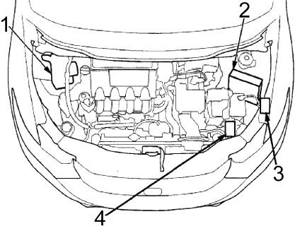
- ABS Modulator-Control Unit (Without VSA), VSA Modulator-Control Unit
- Powertrain Control Module (PCM)
- Relay Box №1
- Relay Box №2
Engine Compartment Fuse Box Diagram
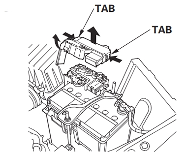
The under-hood main fuses are on the positive terminal of the battery. To open it, push the tabs as shown. These fuses are not serviceable; replace the battery terminal fuse box as an assembly.
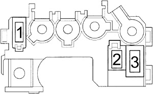
| № | A | Protected Component |
|---|---|---|
| 1 | 100 | DC-DC Converter, Lighting Relay, Power Window Relay, Driver's Door Unlock Relay, Fuses: № 1, 2, 3, 9, 17, 18, 19, 25, 26, 27, 28, 29, 30, 32, 33, 34, 37, 38, 39, 40, 41, 42, 43, 45, 46, 47, 52, 53, 57, 58, 59, 60 |
| 2 | 60 | Electronic Power Steering (EPS) Control Unit |
| 3 | 20 | Fuses: 23, 24 |
Relay Box №1
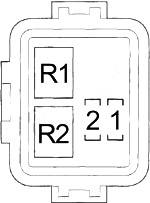
| № | A | Protected Component |
|---|---|---|
| 1 | 15 | Exhaust Side Ignition Coils |
| 2 | 15 | Intake Side Ignition Coils |
| R1 | Fan Control | |
| R2 | PGM-FI Main №2 (Fuel Pump) | |
Relay Box №2
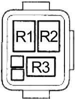
| № | Relay |
|---|---|
| R1 | A/C Condenser Fan |
| R2 | Radiator Fan |
| R3 | A/C Compressor Clutch |
Advertisements