
Advertisements
Fuse box diagram (fuse layout), location, and assignment of fuses and relays Ford Transit (2006, 2007, 2008, 2009, 2010, 2011, 2012, 2013).

Checking and Replacing Fuses
Fuses and circuit breakers protect your vehicle’s electrical system from overloading. If electrical parts in your vehicle are not working, the system may have been overloaded and blown a fuse or tripped a circuit breaker. Before you replace or repair any electrical parts, check the appropriate fuses or circuit breakers.
To check a fuse, look at the silver-colored band inside the fuse. If the band is broken or melted, replace the fuse.
Notice
- Before replacing fuses check that the key has been removed from the ignition and that all the services are switched off and/or disengaged.
- Always disconnect the battery before servicing high current fuses.
- Always replace a fuse with one that has the specified amperage rating. Using a fuse with a higher amperage rating can cause severe wire damage and could start a fire.
- Never replace a broken fuse with anything other than a new fuse. Use always an intact fuse of the same color.
- If a fuse blows again contact a qualified service center.
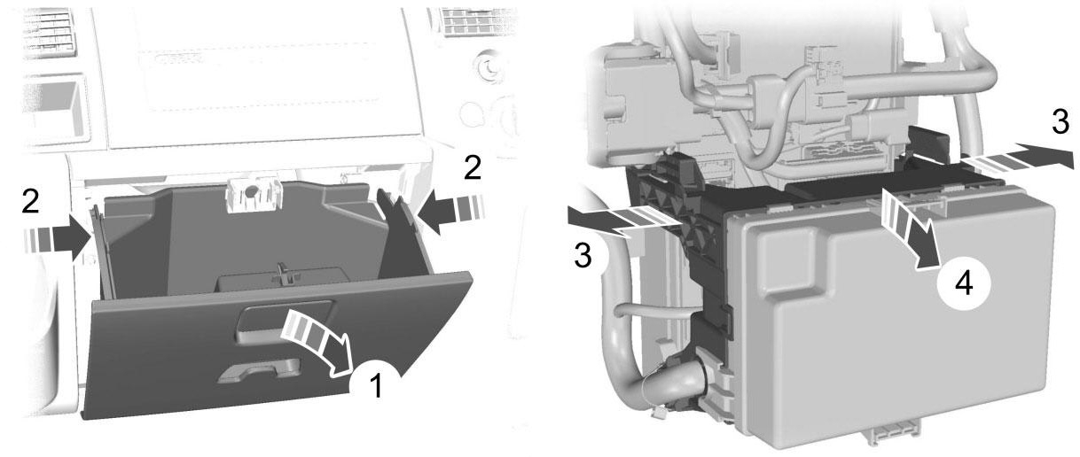
Location
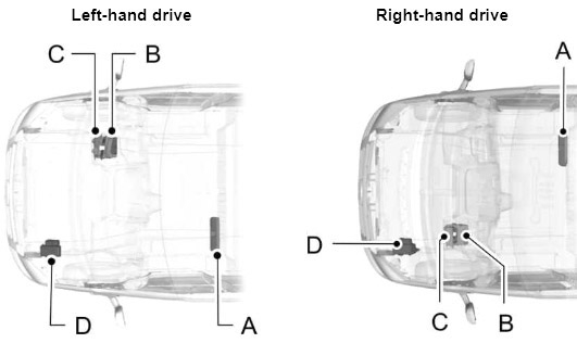
- A) Pre-fuse box
- B) Standard relay box
- C) Passenger compartment junction box
- D) Engine compartment junction box
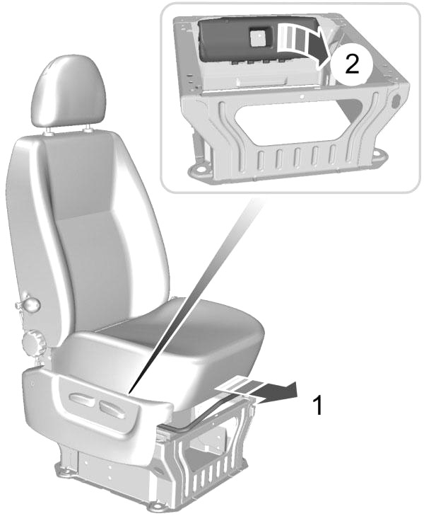
Pre-fuse box
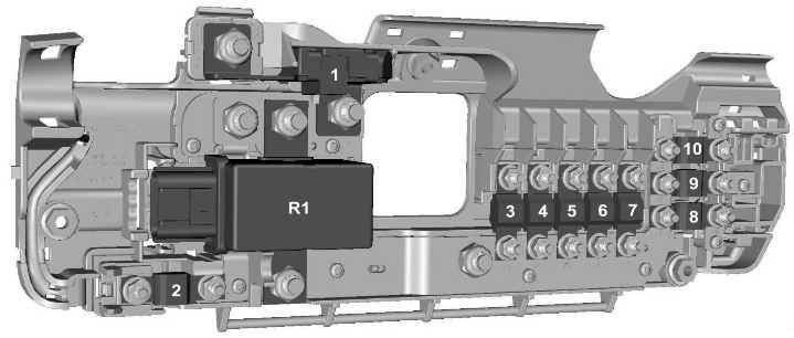
| № | A | Circuits protected |
|---|---|---|
| 1 | 350 | Starter motor and alternator |
| 2 | 60 | Passenger junction box power supply - start relevant / Passenger junction box KL15 for Start-Stop |
| 3 | 100 | Engine junction box power supply - non-start relevant |
| 4 | 40 | Heated front screen right-hand side |
| 5 | 100 | Standard relay box power supply - non-start relevant |
| 6 | 40 | Heated front screen left-hand side |
| 7 | 60 | Passenger junction box power supply - non-start relevant |
| 8 | 60 | Customer connection point |
| 9 | 60 | Customer connection point |
| 10 | 60 | Customer connection point |
| R1 | Second battery disconnect switch | |
Advertisements
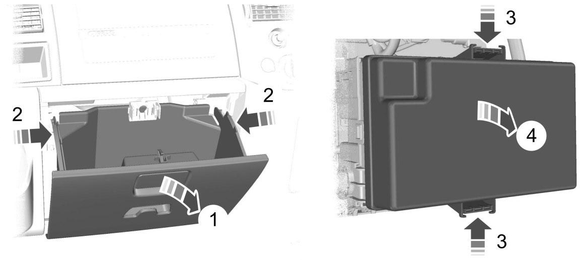
Engine junction box

| № | A | Circuits protected |
|---|---|---|
| 11 | 60 | Engine cooling fan |
| 12 | 30 | Trailer tow and trailer tow module power supply (KL30) |
| 13 | 40 | ABS and ESP pump |
| 14 | - | Not used |
| 15 | 60 | Glow plugs |
| 16 | 60 | Ignition relay (KL15 #3 |
| 17 | 30 | Starter enable |
| 18 | 40 | Ignition feed (KL15) to Passenger junction box (vehicles without Start-Stop) |
| 18 | - | Not used (vehicles with Start-Stop) |
| 19 | - | Not used |
| 20 | 10 | ABS, ESP, steering angle sensor, YAW sensor supply (KL30) |
| 21 | 25 | ABS and ESP valves and control unit |
| 22 | - | Not used |
| 23 | - | Not used |
| 24 | 5 | Fuel pump (without fuel-fired heater) |
| 24 | 20 | Fuel pump (with fuel-fired heater) |
| 25 | - | Not used |
| 26 | 15 | PCM Power |
| 27 | 5 | Fuel pump (with fuel-fired heater) |
| 28 | 5 | T-MAF sensor |
| 29 | 5 | Vaporiser glow plug monitoring |
| 30 | 7.5 | Sonic purge valve |
| 31 | 15 | VAP pump/UEGO |
| 32 | 20 | Vaporiser glow plug |
| 33 | 10 | Reversing lamps |
| 34 | 20 | Trailer KL15 Power supply |
| 35 | - | Not used |
| 36 | 10 | Air conditioning clutch |
| 37 | - | Not used |
| R2 | Glow plugs | |
| R3 | Trailer tow (KL15) | |
| R4 | Starter enable | |
| R5 | Power feed (KL15 #4) | |
| R6 | Power feed (KL15 #3) | |
| R7 | Fuel pump | |
| R8 | Vaporiser glow plug | |
| R9 | Not used | |
| R10 | Air conditioning clutch solenoid | |
Advertisements
Standard relay box
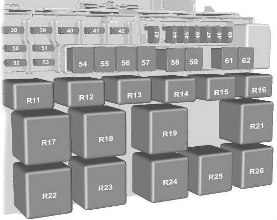
| № | A | Circuits protected |
|---|---|---|
| 38 | 20 | Rear window wiper |
| 39 | 10 | Front and rear air conditioning control |
| 40 | 5 | Not used |
| 41 | 5 | Tachograph |
| 42 | 5 | Headlamp levelling, master light switch (KL15) |
| 43 | 20 | Heated front seats |
| 44 | 20 | Horn |
| 45 | 20 | Auxiliary power point front |
| 46 | 10 | Heated door mirrors, if CAT 1 fitted |
| 47 | 20 | Cigar lighter |
| 48 | 5 | Relay coils supply, power mirrors |
| 49 | 20 | Auxiliary power point rear |
| 50 | 10 | Main beam left-hand side |
| 51 | 10 | Main beam right-hand side |
| 52 | 10 | Dipped beam left-hand side |
| 53 | 10 | Dipped beam right-hand side |
| 54 | 30 | Pre-fuse for dipped beam, main beam, daytime running lamps, tachograph, fuel-fired booster heater blower |
| 55 | 40 | Heater blower motor |
| 56 | 20 | Power windows |
| 57 | 30 | Rear heater blower motor |
| 58 | 30 | Front wiper motor |
| 59 | 30 | Heated rear window, heated door mirrors |
| 60 | - | Not used |
| 61 | 60 | Ignition relay (KL15 #1) |
| 62 | 60 | Ignition relay (KL15 #2) |
| R11 | Headlamp dip beam | |
| R12 | Heated door mirrors (if CAT 1 alarm is fitted), power outlet (if CAT 1 alarm is not fitted) | |
| R13 | Headlamp main beam | |
| R14 | Horn | |
| R15 | Daytime running lamps | |
| R16 | Programmable fuel fired heater | |
| R17 | Heated rear windows and heated door mirrors (or heated rear window left-hand side if Cat 1 alarm is fitted) | |
| R18 | Heated rear window right-hand side if Cat 1 alarm is fitted | |
| R19 | Power feed (KL15 #2) | |
| R20 | PJB KL15 (Start-Stop only) | |
| R21 | Power feed (KL15 #1) | |
| R22 | Heated windscreen right-hand side | |
| R23 | Windscreen wiper high and low function | |
| R24 | Rear window wiper | |
| R25 | Windscreen wiper on and off function | |
| R26 | Heated windscreen left-hand side | |
Advertisements
Passenger junction box
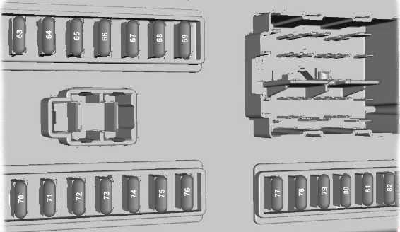
| № | A | Circuits protected |
|---|---|---|
| 1 | 350 | Starter motor and alternator |
| 2 | 60 | Passenger junction box power supply - start relevant / Passenger junction box KL15 for Start-Stop |
| 3 | 100 | Engine junction box power supply - non-start relevant |
| 4 | 40 | Heated front screen right-hand side |
| 5 | 100 | Standard relay box power supply - non-start relevant |
| 6 | 40 | Heated front screen left-hand side |
| 7 | 60 | Passenger junction box power supply - non-start relevant |
| 8 | 60 | Customer connection point |
| 9 | 60 | Customer connection point |
| 10 | 60 | Customer connection point |
| R1 | Second battery disconnect switch | |
Auxiliary fuses
| № | A | Circuits protected | Location |
|---|---|---|---|
| 83 | 10 | Trailer tow module | Left-hand side footwell |
| 84 | 7.5 | DPF glow plug sensing | Below the engine compartment junction box |
Advertisements