
Advertisements
Fuse box diagram (fuse layout), location, and assignment of fuses and relays Ford Ranger T6 (2011, 2012, 2013, 2014, 2015, 2016, 2017, 2018).
Checking and Replacing Fuses
Fuses and circuit breakers protect your vehicle’s electrical system from overloading. If electrical parts in your vehicle are not working, the system may have been overloaded and blown a fuse or tripped a circuit breaker. Before you replace or repair any electrical parts, check the appropriate fuses or circuit breakers.
To check a fuse, look at the silver-colored band inside the fuse. If the band is broken or melted, replace the fuse.
Notice
- Before replacing fuses check that the key has been removed from the ignition and that all the services are switched off and/or disengaged.
- Always disconnect the battery before servicing high current fuses.
- Always replace a fuse with one that has the specified amperage rating. Using a fuse with a higher amperage rating can cause severe wire damage and could start a fire.
- Never replace a broken fuse with anything other than a new fuse. Use always an intact fuse of the same color.
- If a fuse blows again contact a qualified service center.
Location
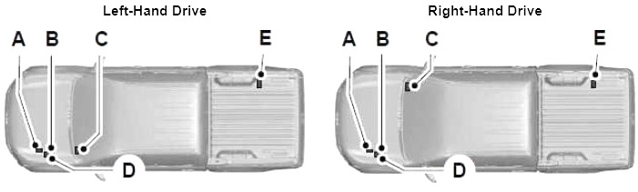
- A) Pre-fuse box.
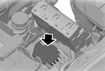
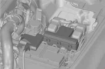
- B) Engine compartment fuse box (Power Distribution Box – PDB)
- C) Passenger compartment fuse box
- D) High current fuse box (below the PDB)
- E) The auxiliary fuse box (if equipped)
Type 1
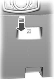
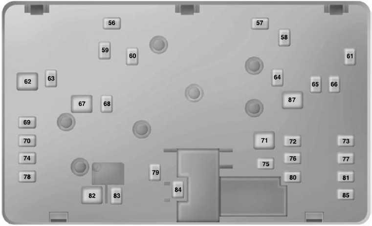
Instrument Panel Fuse Box
The fuse box is located below and outboard of the steering column behind the access cover.
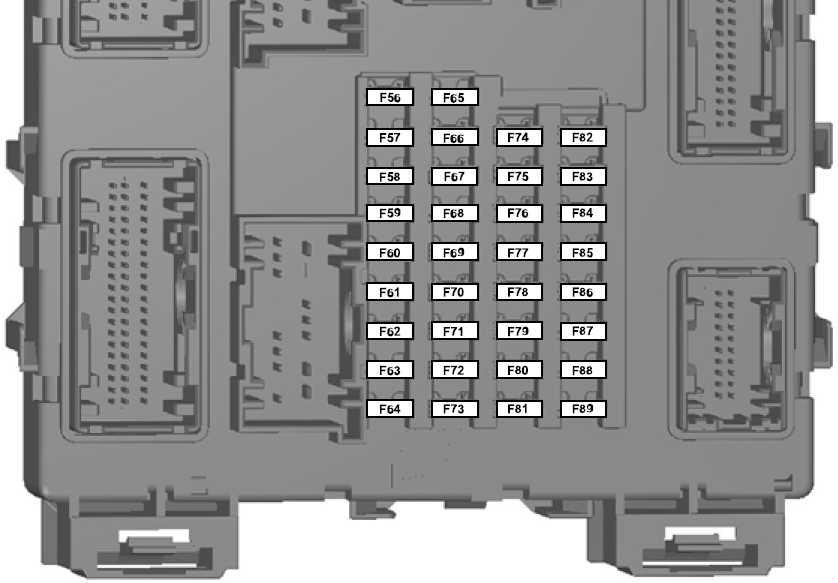
| № | A | Protected Components |
|---|---|---|
| 56 | 20 | Fuel pump |
| 57 | - | Not used |
| 58 | - | Not used |
| 59 | 5 | Passive anti-theft system (PATS) |
| 60 | 10 | Interior lamp, driver's door switch pack, mood lights, puddle lights, automatic shifter, footwell lamp |
| 61 | - | Not used |
| 62 | 5 | Rain sensor module |
| 63 | 5 | Tachograph |
| 64 | - | Not used |
| 65 | - | Not used |
| 66 | 20 | Driver's door unlock, central double locking |
| 67 | 5 | Stop lamp switch |
| 68 | - | Not used |
| 69 | 5 | Instrument cluster, integrated control module (ICP), tracking and blocking module |
| 70 | 20 | Central locking |
| 71 | 5 | Air conditioning |
| 72 | 7.5 | Alarm horn |
| 73 | 5 | On-board diagnostics II |
| 74 | 20 | Main beam |
| 75 | 15 | Front fog lamps |
| 76 | 10 | Reversing lamp, rear view mirror |
| 77 | 20 | Washer pump |
| 78 | 5 | Ignition switch |
| 79 | 15 | Radio, Audio signal DIN, FSAO audio, multi-function display |
| 80 | 20 | Multi-function display, Hi audio, bluetooth audio (2015-2018), brake valve closing (BVC) module (2011-2014) |
| 81 | 5 | Interior motion sensor |
| 82 | 20 | Washer pump ground |
| 83 | 20 | Central locking ground |
| 84 | 20 | Driver's door unlock, central double locking ground |
| 85 | 7.5 | Instrument cluster, parking aid module, rearview camera, manual air conditioning, rear view mirror, tracking and blocking module |
| 86 | 10 | Restraint system, passenger air-bag deactivation indicator |
| 87 | 7.5 | Tachograph |
| 88 | - | Not used |
| 89 | - | Not used |
Advertisements
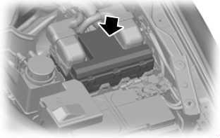
Engine Compartment Fuse Box
The power distribution box is located in the engine compartment.
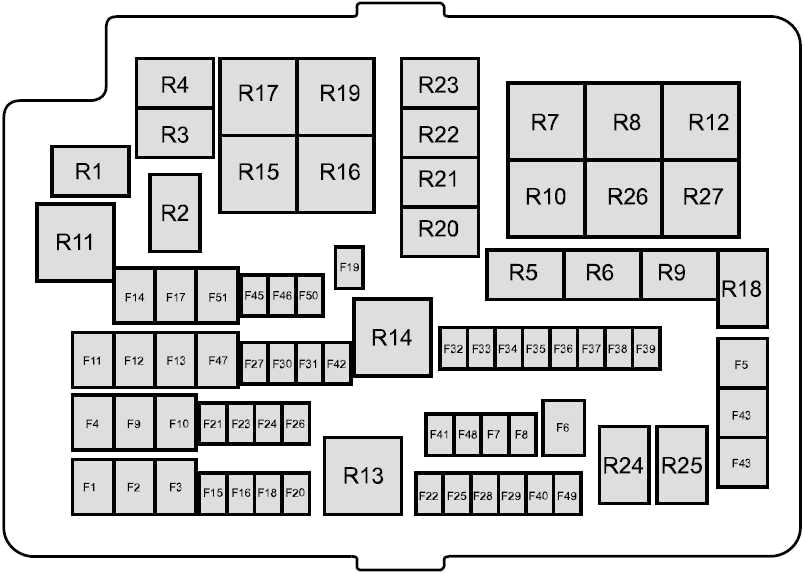
| № | A | Protected Components |
|---|---|---|
| 1 | 60 | Passenger compartment fuse box supply (Battery) |
| 2 | 60 | Passenger compartment fuse box supply (Battery) |
| 3 | 50 | Petrol: Engine cooling fan |
| 60 | Diesel: Glow plug control module | |
| 4 | 40 | Anti-lock brake system module |
| 5 | 30 | Power windows (front and rear) |
| 6 | 25 | 2011-2014: Four wheel drive (4WD) motor ground |
| 7 | - | Not used |
| 8 | - | Not used |
| 9 | 20 | Power seats |
| 10 | 20 | 2015-2018: Auxiliary power socket instrument panel, console top |
| 25 | 2011-2014: Electric windows (front) | |
| 11 | 30 | Blower motor |
| 12 | 25 | Four wheel drive (4WD) motor power |
| 13 | 20 | Starter solenoid |
| 14 | 20 | Heated rear window |
| 15 | 10 | Petrol: Flex-fuel pump |
| 20 | Diesel (2013-2016): Vaporizer glow plug | |
| 15 | Diesel (2011-2012 and 2017-2018): Vaporizer glow plug | |
| 16 | 10 | Air conditioning clutch |
| 17 | 25 | Power windows (front) |
| 18 | 25 | Windscreen wiper motor |
| 19 | 25 | 2011-2014: Windscreen wiper motor ground |
| 20 | 20 | Cigar lighter |
| 21 | 15 | Horn |
| 22 | 15 | 2011-2016: Fuel injectors, flex-fuel valve |
| 10 | 2017-2018: Fuel injectors, flex-fuel valve. | |
| 23 | 10 | Differential lock solenoid |
| 24 | 20 | 2011-2014: Auxillary power socket (front console) |
| 25 | 15 | Ignition coils, temperature and mass air flow sensor, glow plug module, vacuum control valve (VCV), electronic vacuum regulator valve (EVRV) |
| 26 | 7.5 | Electronic control module (ECM) |
| 27 | 10 | Transmission control module (TCM) |
| 28 | 10 | Heated exhaust gas oxygen, universal heated exhaust gas oxygen-sensor, relay coils |
| 29 | 15 | Electronic control module (ECM) |
| 30 | 5 | 2015-2018: Battery monitoring sensor |
| 15 | 2011-2014: Battery monitoring sensor | |
| 31 | 20 | Auxiliary power socket (rear console) |
| 32 | 5 | Air conditioning pressure switch |
| 33 | 10 | Transmission control module (TCM) |
| 34 | 5 | 2014-2018: Crew chief module |
| 2011-2013: PTC heater (where fitted) | ||
| 35 | 20 | Passenger compartment fuse box supply (Ignition) |
| 36 | 5 | Anti-lock brake system module |
| 37 | 10 | Headlamp leveling |
| 38 | 20 | 2011-2014: Heated seat |
| 39 | 10 | Power mirrors |
| 40 | 10 | Vapourizer pump |
| 41 | 10 | Heated mirrors |
| 42 | 10 | Alarm horn |
| 43 | 30 | 2011-2014: Heated windscreen (right) |
| 44 | 30 | 2011-2014: Heated windscreen (left) |
| 45 | 25 | Anti-lock brake system module |
| 46 | 20 | 2011-2014: Auxillary power socket (bedliner (floor console)) |
| 20 | 2015-2018: Battery isolator | |
| 47 | 40 | Trailer tow module |
| 48 | - | Not used |
| 49 | - | Not used |
| 50 | 5 | Ignition relay, relay coils |
| 51 | 20 | 2011-2018: Trailer Tow (12/13pin Batt feed / Permanent Live) |
| 30 | 2011-2014: Electric windows (rear) | |
| R1 | Key interlock | |
| R2 | Wiper on or off | |
| R3 | Horn | |
| R4 | Air conditioning clutch | |
| R5 | Differential lock | |
| R6 | Wiper Hi or Lo | |
| R7 | Engine cooling fan low | |
| R8 | Engine cooling fan high | |
| R9 | Flex-fuel pump, vaporizer glow plug | |
| R10 | Heated rear window | |
| R11 | 2011-2014: Heated windscreen | |
| R12 | Not used | |
| R13 | Electronic control module (ECM) power hold | |
| R14 | Ignition | |
| R15 | 4WD motor 2 (clockwise) | |
| R16 | 4WD motor 1 (counter clockwise) | |
| R17 | 4WD motor | |
| R18 | Security horn | |
| R19 | Starter | |
| R20 | Not used | |
| R21 | Not used | |
| R22 | Not used | |
| R23 | Not used | |
| R24 | Not used | |
| R25 | Not used | |
| R26 | Blower motor | |
| R27 | Power seat | |
Auxiliary Fuse Box
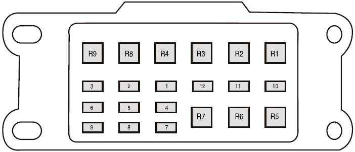
| № | A | Protected Components |
|---|---|---|
| 1 | 25 | Driving Light |
| 2 | 15 | Position lamp |
| 3 | 10 | LED beacon |
| 4 | 15 | Work lights |
| 5 | 20 | Spare |
| 6 | 20 | Power point |
| 7 | 15 | Reversing lamp |
| 8 | 15 | Direction indicators, stop lamp |
| 9 | 5 | Crew chief |
| 10 | 5 | Disable fuse (isolator ground) |
| 11 | - | Not used |
| 12 | - | Not used |
| R1 | Work lights | |
| R2 | LED beacon | |
| R3 | Spare | |
| R4 | Position lamp | |
| R5 | Direction indicator (left) | |
| R6 | Direction indicator (right) | |
| R7 | Stop lamp | |
| R8 | Not used | |
| R9 | Not used | |
Advertisements
Type 2
Instrument Panel Fuse Box
The fuse box is located below and outboard of the steering column behind the access cover.
| № | A | Protected Components |
|---|---|---|
| 1 | 10 | Glove box lamp, Map lamp, Battery saver, Overhead console, Sun visor, Grab handle, Automatic transmission gear shifter (diesel) |
| 2 | 7.5 | Not used |
| 3 | 20 | Driver door latch / Fuel flap unlock relay, Door Double / Aux lock relay |
| 4 | 5 | Not used |
| 5 | 20 | Not used |
| 6 | 10 | Not used |
| 7 | 10 | Not used |
| 8 | 10 | Security horn |
| 9 | 10 | Not used |
| 10 | 5 | Not used |
| 11 | 5 | Interior motion sensor |
| 12 | 7.5 | Electronic control panel, Climate control |
| 13 | 7.5 | Instrument cluster, Data link connector, Steering column control module |
| 14 | 10 | Not used |
| 15 | 10 | Gateway module/smart data link connector, OBDII (RHD) |
| 16 | 15 | Child lock |
| 17 | 5 | Battery backed sounder, Tracking and Blocking Module |
| 18 | 5 | Ignition switch |
| 19 | 7.5 | Not used |
| 20 | 7.5 | Headlamp control module |
| 21 | 5 | Humidity and in car temperature sensor |
| 22 | 5 | Not used |
| 23 | 10 | Inverter, Driver door window, Central locking system |
| 24 | 20 | Central locking system |
| 25 | 30 | Driver door control module (power window - one touch up/down all doors) |
| Driver door power window switch memory (with one touch up/down driver only) | ||
| 26 | 30 | Passenger door control module (power window) (one touch up/down) |
| 27 | 30 | Not used |
| 28 | 20 | Not used |
| 29 | 30 | Left rear door control module (power window) (one touch up/down) |
| 30 | 30 | Right rear door control module (power window) (one touch up/down) |
| 31 | 15 | Tachograph |
| 32 | 10 | Radio transceiver module, SYNC module, GPS, Multi-function display, Door entry remote |
| 33 | 20 | Audio unit |
| 34 | 30 | Starter relay |
| 35 | 5 | Restraints control module |
| 36 | 15 | Auto-dimming interior mirror |
| 37 | 15 | Not used |
| 38 | 30 | Power windows (without door control module) (one touch up/down - driver only) |
Engine Compartment Fuse Box
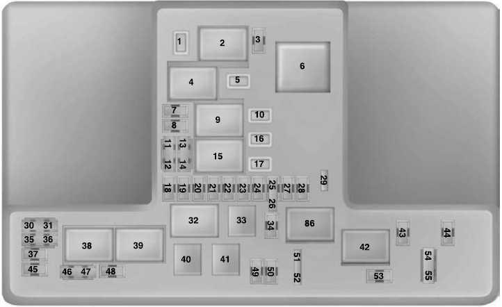
| № | A | Protected Components |
|---|---|---|
| 1 | 25 | Smart wiper module |
| 3 | 15 | Rain sensor |
| 5 | 20 | Auxiliary power point (Rear of centre console) |
| 7 | 20 | Powertrain control module |
| 8 | 20 | Variable intake manifold, Powertrain control module, Evaporative emission canister purge valve, Heated oxygen sensor, Catalyst monitoring sensor (CMS) |
| 10 | 20 | Auxiliary power point (Cigar lighter) |
| 11 | 15 | Powertrain control module, Ignition coil |
| 12 | 15 | 2.2 L and 3.2 L Duratorq: Fan drive, Powertrain control module, Glow plugs |
| 13 | 15 | 2.5 L Duratec: Heater, Fuel injectors |
| 14 | 15 | 2.2 L Duratorq: Powertrain control module, PCV Heater |
| 16 | 20 | Auxiliary power point (Cigar lighter 2) |
| 17 | 20 | Auxiliary power point (Rear cargo area) |
| 18 | 10 | 2.5 L Duratec: Powertrain control module, Keep alive power |
| 19 | 10 | Electronic power assist steering |
| 20 | 10 | Lighting control, Headlamp leveling |
| 21 | - | Not used |
| 22 | 10 | A/C clutch |
| 23 | 15 | Head-up display, Rear parking aid camera, Adaptive cruise control |
| 24 | 5 | Air Conditioning pressure switch (Manual transmission vehicles only) |
| 25 | 10 | Anti-lock brake system |
| 26 | 10 | Mirror adjust switch, Tachograph |
| 27 | 5 | Auxiliary Heater |
| 28 | 10 | Powertrain control module |
| 29 | - | Not used |
| 30 | - | Not used |
| 31 | - | Not used |
| 34 | 15 | Stop lamp (Center high mount) |
| 35 | 15 | 2.2 L Duratorq and 3.2 L Duratorq: Transmission control module |
| 36 | - | Not used |
| 37 | 10 | Heated exterior mirror |
| 43 | - | Not used |
| 44 | - | Not used |
| 45 | 10 | 2.5 L Duratec: Fuel injectors |
| 46 | 10 | Not used |
| 47 | 10 | Brake pedal switch |
| 48 | 20 | Horn |
| 49 | - | Not used |
| 50 | - | Not used |
| 51 | - | Not used |
| 52 | - | Not used |
| 53 | 10 | Rear differential lock |
| 54 | - | Not used |
| 55 | - | Not used |
| 2 | Starter motor solenoid relay | |
| 4 | Blower motor relay | |
| 6 | 2.5 L Duratec: Cooling fan relay (High-speed cooling fan) | |
| 9 | Powertrain control module relay | |
| 15 | Starter relay | |
| 32 | 2.5 L Duratec and 2.2 L Duratorq: Fuel pump relay | |
| 33 | A/C clutch relay | |
| 38 | 2.5 L Duratec: Cooling fan relay (Low speed) | |
| 39 | Four wheel drive power relay | |
| 40 | Stop lamp relay (Center high mount) | |
| 41 | Horn relay | |
| 42 | Four wheel drive motor № 2 relay | |
| 86 | Four wheel drive motor № 1 relay | |
Advertisements
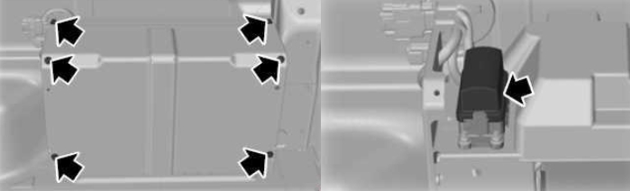
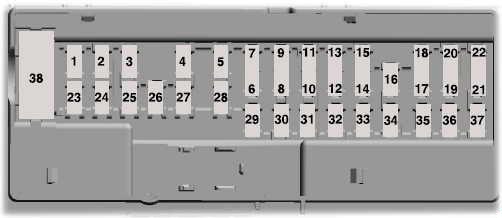
There are fuses located on the bottom of the fuse box.
To access the bottom of the fuse box, do the following:
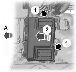
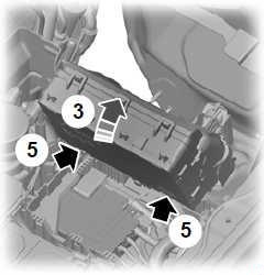
- Release the two latches, located on both sides of the fuse box.
- Raise the inboard side of the fuse box from the cradle.
- Move the fuse box toward the center of the engine compartment.
- Pivot the outboard side of the fuse box to access the bottom side.
- Release the two latches to open the fuse cover.
| № | A | Protected Components |
|---|---|---|
| 56 | - | Not used |
| 57 | - | Not used |
| 58 | - | Not used |
| 59 | 25 | Four Wheel Drive |
| 60 | 30 | Fuel Pump Control Module |
| 61 | 30 | Windshield Defrost (left) |
| 62 | 50 | Body control module 1 (lighting) |
| 63 | 30 | 2.5 L Duratec: Low-speed cooling fan |
| 64 | 20 | Trailer tow connector |
| 65 | 20 | Heated front seats |
| 66 | 30 | Windshield Defrost (right) |
| 67 | 50 | Body control module 2 |
| 68 | 20 | Rear window defroster |
| 69 | 30 | Anti-lock brake system (Valves) |
| 70 | - | Not used |
| 71 | 50 | 2.5 L Duratec: High-speed cooling fan |
| 72 | - | Not used |
| 73 | - | Not used |
| 74 | 20 | Driver power seat |
| 75 | - | Not used |
| 76 | - | Not used |
| 77 | - | Not used |
| 78 | - | Not used |
| 79 | 40 | Blower motor |
| 80 | - | Not used |
| 81 | 40 | Inverter |
| 82 | 60 | Anti-lock brake system (Pump) |
| 83 | 25 | Windshield wiper motor |
| 84 | 30 | Starter motor solenoid |
| 85 | - | Not used |
| 87 | 40 | Trailer module |
High Current Fuse Box
| № | A | Protected Components |
|---|---|---|
| 1 | 70 | 2.5 L Duratec: Heater Control Unit (cold start) |
| 60 | 2.2 L Duratorq and 3.2 L Duratorq: Glow plug module. | |
| 2 | 125 | Body control module 1 |
| 3 | 50 | 2.5 L Duratec: Body control module 2 |
| 2.2 L Duratorq and 3.2 L Duratorq: Body control module, Rear parking aid camera, Voltage quality module, Adaptive cruise control, Head-up display | ||
| 4 | - | Busbar through to power distribution box |
| 5 | 100 | Auxiliary heater (if equipped) |
Pre-fuse box (Battery Mounted Fuse Link)
| № | A | Protected Components |
|---|---|---|
| 1 | 225 | Body control module 1 |
| 2 | 125 | Electronic power assist steering. |
Advertisements