
Advertisements
Fuse box diagram (fuse layout), location and assignment of fuses and relays Ford Mustang (2010, 2011, 2012, 2013, 2014).
Checking and Replacing Fuses
Fuses and circuit breakers protect your vehicle’s electrical system from overloading. If electrical parts in your vehicle are not working, the system may have been overloaded and blown a fuse or tripped a circuit breaker. Before you replace or repair any electrical parts, check the appropriate fuses or circuit breakers.
To check a fuse, look at the silver-colored band inside the fuse. If the band is broken or melted, replace the fuse.
Notice
- Before replacing fuses check that the key has been removed from the ignition and that all the services are switched off and/or disengaged.
- Always disconnect the battery before servicing high current fuses.
- Always replace a fuse with one that has the specified amperage rating. Using a fuse with a higher amperage rating can cause severe wire damage and could start a fire.
- Never replace a broken fuse with anything other than a new fuse. Use always an intact fuse of the same color.
- If a fuse blows again contact a qualified service center.
Passenger Compartment Fuse Box Diagram
The fuse panel is located in the lower passenger side area behind the kick panel. Open the trim panel door and remove the fuse cover to access the fuses.
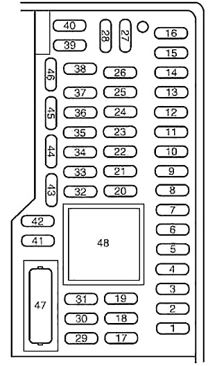
| № | A | Description |
|---|---|---|
| 1 | 30 | Driver rear window (convertible only) |
| 2 | 15 | 2010: Brake On/Off (BOO) power |
| 3 | 15 | SYNC |
| 4 | 30 | Passenger rear window (convertible only) |
| 5 | 10 | Brake transmission shift interlock (BTSI) |
| 6 | 20 | Turn signals, Hazard flashers |
| 7 | 10 | Left low beam headlamp |
| 8 | 10 | Right low beam headlamp |
| 9 | 15 | Courtesy lamps |
| 10 | 15 | Switch illumination, Pony projection lights (2013-2014) |
| 11 | 10 | Security module |
| 12 | 7.5 | Power mirrors |
| 13 | 5 | Not used (Spare) |
| 14 | 10 | Center information display, Electronic finish panel, GPS |
| 15 | 10 | Climate control |
| 16 | 15 | Not used (Spare) |
| 17 | 20 | Power door locks, Trunk release (2011-2014) |
| 18 | 20 | Not used (Spare) |
| 19 | 25 | 2010-2012: Navigation amp |
| 20 | 15 | Diagnostic connector |
| 21 | 15 | Fog lamps |
| 22 | 15 | Park lamps, License lamps |
| 23 | 15 | High beam headlamps |
| 24 | 20 | Horn |
| 25 | 10 | Demand lighting (battery saver), Visor vanity lamps (2012-2014), Gauge pack (2012) |
| 26 | 10 | Cluster (battery) |
| 27 | 20 | Ignition switch feed |
| 28 | 5 | Audio mute (Start) |
| 29 | 5 | Camera (Run/Start) |
| 30 | 5 | 2011-2014: Temperature sensor motor |
| 31 | 10 | Restraints control module (RCM) |
| 32 | 10 | 2012-2014: Reverse parking aid, Vehicle dynamics control module (Shelby only (2013-2014)) |
| 33 | 10 | Not used (Spare) |
| 34 | 5 | Electronic stability control, Steering angle (2010) |
| 35 | 10 | Auxiliary body module (ABM) Run/Start |
| 36 | 5 | Passive anti-theft system (PATS) |
| 37 | 10 | 2013-2014: Rear defroster relay coil |
| 38 | 20 | Not used (Spare) |
| 39 | 20 | Radio/Navigation |
| 40 | 20 | Not used (Spare) |
| 41 | 15 | Accessory delay (windows, automatic dimming rear view mirror [including microphone and compass] and door switch III) |
| 42 | 10 | Not used (Spare) |
| 43 | 10 | Heated seat relay coils |
| 44 | 10 | Not used (Spare) |
| 45 | 5 | Wiper relay and module, Blower relay |
| 46 | 7.5 | Passenger airbag deactivation indicator (PADI), Occupant classification sensor (OCS) |
| 47 | 30 | Circuit Breaker: Not used (Spare) |
| 48 | Accessory delay relay (windows, automatic dimming rear view mirror [including microphone and compass] and door switch III) | |
Auxiliary relay with heated seats
On heated seat equipped vehicles, there is a relay box located under the driver seat containing two relays for the driver and passenger heated seats.
Advertisements
Engine Compartment Fuse Box Diagram
The power distribution box is located in the engine compartment. The power distribution box contains high-current fuses that protect your vehicle’s main electrical systems from overloads.
Do not probe the contacts for the fuses and relays in the power distribution box as damage will occur, causing improper, or loss of, electrical functionality.
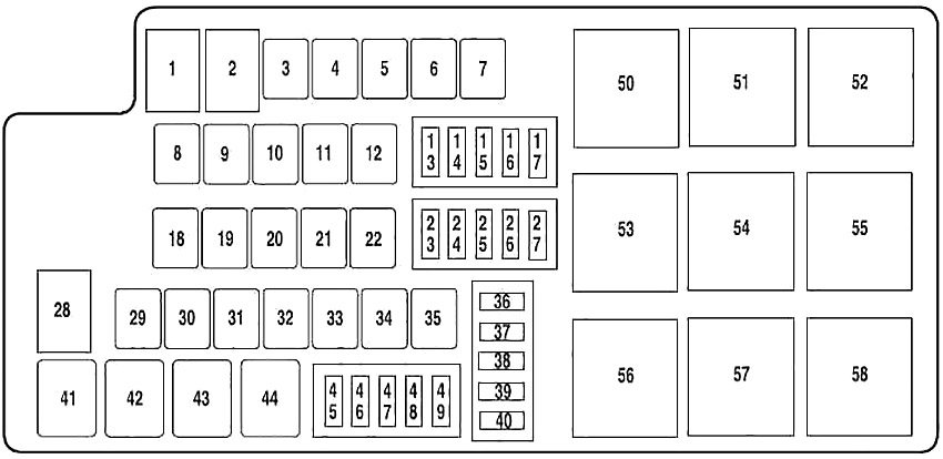
| № | A | Description |
|---|---|---|
| 1 | 80 | Passenger compartment fuse panel |
| 2 | — | Not used |
| 3 | — | Not used |
| 4 | 30 | Blower motor relay |
| 5 | 20 | Powerpoint (body) |
| 6 | 40 | Rear defroster |
| 7 | 40 | Cooling fan relay |
| 8 | 40 | Anti-lock brake system (ABS) pump |
| 9 | 30 | Wipers |
| 10 | 30 | ABS valve |
| 11 | — | Not used |
| 12 | 20 | 2013-2014: Differential fluid pump (Shelby only) |
| 13 | 15 | 2010: Fuel pump relay |
| 20 | 2011-2014: Fuel pump relay (non-Shelby) | |
| 25 | 2011-2014: Fuel pump relay (Shelby only) | |
| 14 | 15 | 2010: Fuel pump relay #2 (Shelby only) |
| 20 | 2013-2014: Fuel pump relay #2 (Shelby only) | |
| 15 | 10 | Intercooler pump relay (Shelby only) |
| 16 | 20 | Heated seats |
| 17 | 10 | Alternator sense |
| 18 | 20 | Auxiliary body module (ABM) |
| 19 | 30 | Starter relay |
| 20 | 30 | Rear amplifier (Shaker 1000 radio / Shaker Pro radio) |
| 21 | 30 | Powertrain relay |
| 22 | 20 | PowerPoint (instrument panel) |
| 23 | 10 | Powertrain control module (PCM) keep-alive power |
| 24 | 10 | 2011-2014: Brake on/off power |
| 25 | 10 | A/C compressor relay |
| 26 | 20 | Left high intensity discharge headlamp relay |
| 27 | 20 | Right high intensity discharge headlamp relay |
| 28 | — | Not used |
| 29 | 30 | Passenger front window |
| 30 | — | Not used |
| 31 | 30 | Passenger power seat |
| 32 | 30 | Driver power seat |
| 33 | 30 | Front amplifier (Shaker radio) |
| 34 | 30 | Driver front window motor |
| 35 | 40 | Convertible top motor |
| 36 | — | Diode: Fuel diode |
| 37 | — | Not used |
| 38 | 15 | 2011-2014: Fuel injectors (Shelby only) |
| 39 | 5 | 2010-2012: Rear defroster coil (Run/Start) |
| 2013-2014: Heated mirrors | ||
| 40 | 15 | Powertrain control module Vehicle Power 4 - ignition coil |
| 45 | 5 | Powertrain control module Run/Start |
| 46 | 5 | Powertrain control module Vehicle Power 3 - general powertrain components |
| 47 | 15 | Powertrain control module Vehicle Power 1 |
| 48 | 15 | Powertrain control module Vehicle Power 5 -transmission |
| 49 | 15 | Powertrain control module Vehicle Power 2 - emissions related powertrain components |
| 41 | Fuel pump relay | |
| 42 | Intercooler pump relay (Shelby only) | |
| 43 | A/C compressor relay | |
| 44 | Fuel pump relay #2 (Shelby only) | |
| 50 | Cooling fan relay (high) | |
| 51 | Blower motor relay | |
| 52 | Starter relay | |
| 53 | Rear defroster relay | |
| 54 | Front wiper relay | |
| 55 | Cooling fan relay (low) | |
| 56 | Not used (Spare) | |
| 57 | PCM relay | |
| 58 | 2013-2014: Differential fluid pump (Shelby only) | |
Advertisements