
Advertisements
Fuse box diagram (fuse layout), location and assignment of fuses and relays Ford Mustang (1999, 2000, 2001, 2002, 2003, 2004).

Checking and Replacing Fuses
Fuses and circuit breakers protect your vehicle’s electrical system from overloading. If electrical parts in your vehicle are not working, the system may have been overloaded and blown a fuse or tripped a circuit breaker. Before you replace or repair any electrical parts, check the appropriate fuses or circuit breakers.
To check a fuse, look at the silver-colored band inside the fuse. If the band is broken or melted, replace the fuse.
Notice
- Before replacing fuses check that the key has been removed from the ignition and that all the services are switched off and/or disengaged.
- Always disconnect the battery before servicing high current fuses.
- Always replace a fuse with one that has the specified amperage rating. Using a fuse with a higher amperage rating can cause severe wire damage and could start a fire.
- Never replace a broken fuse with anything other than a new fuse. Use always an intact fuse of the same color.
- If a fuse blows again contact a qualified service center.
Instrument Panel Fuse Box Diagram
The fuse panel is located below and to the left of the steering wheel by the brake pedal. Remove the panel cover to access the fuses.
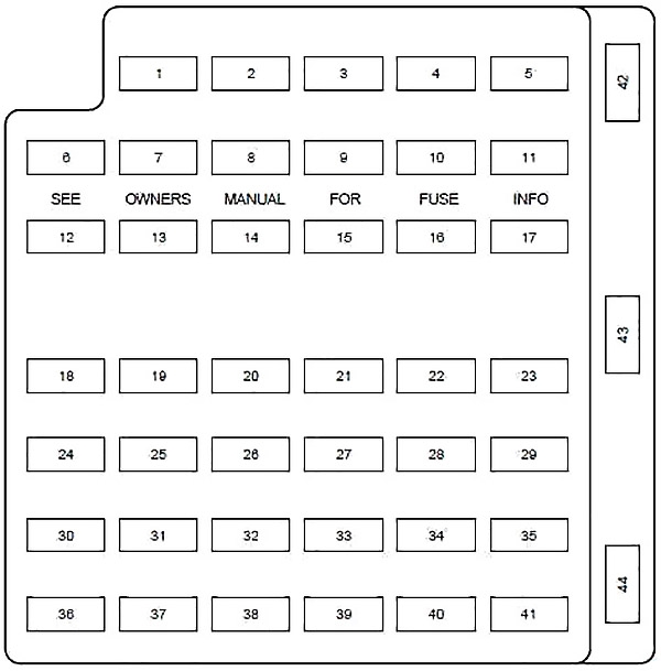
| № | A | Description |
|---|---|---|
| 1 | 20 | Cigar Lighter |
| 2 | 20 | Engine Controls |
| 3 | — | Not Used |
| 4 | 10 | RH Low Beam Headlamp |
| 5 | 15 | Instrument Cluster, Traction Control Switch |
| 6 | 20 | Starter Motor Relay |
| 7 | 15 | GEM, Interior Lamps |
| 8 | 20 | Engine Controls |
| 9 | 30 | 2002-2004: Mach 460 subwoofers |
| 10 | 10 | LH Low Beam Headlamp |
| 11 | 15 | Back-up Lamps |
| 12 | 2 | 2003-2004: Heated PCV |
| 13 | 15 | Electronic Flasher |
| 14 | — | Not Used |
| 15 | 15 | Power Lumbar |
| 16 | — | Not Used |
| 17 | 15 | Speed Control Servo, Shift Lock Actuator |
| 18 | 15 | Electronic Flasher |
| 19 | 15 | Power Mirror Switch, GEM, Anti-Theft. Relay, Power Door Locks, Door Ajar Switches |
| 20 | 15 | Convertible Top Switch |
| 21 | 5 | Instrument Cluster and Engine Control Memory |
| 22 | — | Not Used |
| 23 | 15 | A/C Clutch, Defogger Switch |
| 24 | 30 | Climate Control Blower Motor |
| 25 | 25 | Luggage Compartment Lid Release |
| 26 | 30 | WiperAVasher Motor, Wiper Relays |
| 27 | 25 | Radio |
| 28 | 15 | GEM, Overdrive Cancel Switch |
| 29 | 15 | ABS Module |
| 30 | 15 | Daytime Running Lamps (DRL) module |
| 31 | 10 | Data Link Connector |
| 32 | 15 | Radio, CD Player (1999-2001), GEM |
| 33 | 15 | Stop Lamp Switch, Speed Control Deactivation Switch |
| 34 | 20 | Instrument Cluster, CCRM, Data Link Connector, Securilock Transciever Module |
| 35 | 15 | Shift Lock Actuator, PCM, Speed Control Servo, ABS Module |
| 36 | 15 | Airbag Control Module |
| 37 | 10 | Adjustable Illumination |
| 38 | 20 | Highbeams |
| 39 | 5 | GEM |
| 40 | — | Not Used |
| 41 | 15 | Brake Lamp |
| 42 | — | Not Used |
| 43 | 20 | Circuit Breaker: Power Windows |
| 44 | — | Not Used |
Advertisements
Engine Compartment Fuse Box Diagram
The power distribution box is located in the engine compartment.
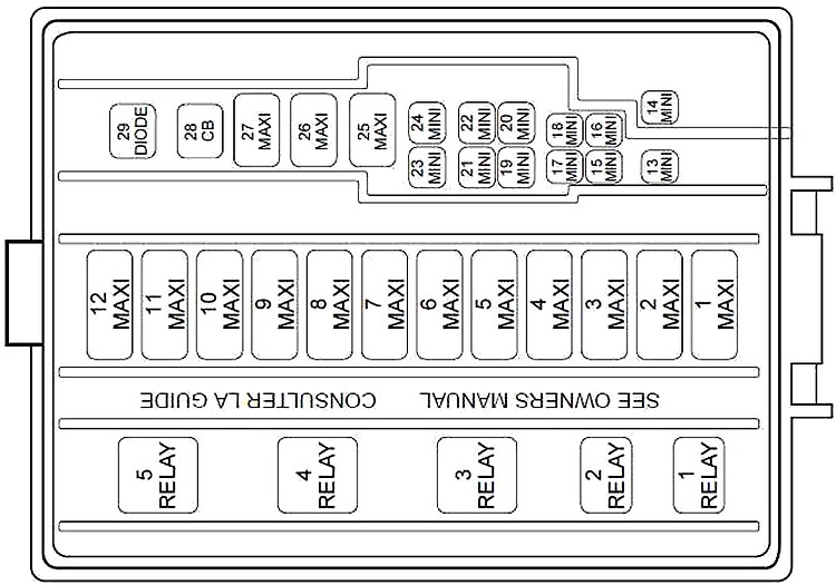
| № | A | Description |
|---|---|---|
| 1 | 50 | V8: Electric Cooling Fan Motor |
| 30 | V6: Electric Cooling Fan Motor (Circuit Breaker) | |
| 2 | 30 | Headlamps |
| 3 | 40 | Starter Motor Relay, Ignition Switch |
| 4 | 40 | Ignition Switch |
| 5 | 40 | Ignition Switch |
| 6 | 40 | I/P fuse panel, Instrument cluster, Powertrain Control Module (PCM) |
| 7 | 30 | 1999-2002: Secondary Air Injection (3.8L only) |
| 8 | 50 | ABS Module |
| 9 | 20 | Auxiliary Power Point |
| 10 | 30 | Parklamps |
| 11 | 30 | Rear Window Defrost Control |
| 12 | 40 | Power Windows (1999-2002), Power Locks |
| 13 | 30 | 2003-2004: MACH 1000 right amplifiers |
| 14 | 20 | Fuel Pump |
| 15 | 10 | 1999-2002: Radio |
| 30 | 2003-2004: MACH 1000 left amplifiers | |
| 16 | 20 | Horn |
| 17 | 20 | Anti-Lock Brake System |
| 18 | 25 | Power Seats |
| 19 | 10 | 2002-2004: Intercooler pump (Cobra only) |
| 20 | 20 | Generator |
| 21 | — | Not Used |
| 22 | — | Not Used |
| 23 | — | Not Used |
| 24 | 20 | A/C Pressure |
| 25 | — | Not Used |
| 26 | 30 | PCM |
| 27 | 20 | DRL Module, Foglamp Relay |
| 28 | 25 | Circuit Breaker:Convertible Top |
| R1 | Fog Lamp Interrupt | |
| R2 | Int. Wiper | |
| R3 | Wiper HI/LO | |
| R4 | Starter | |
| R5 | Fog Lamps | |
Advertisements