
Advertisements
Fuse box diagram (fuse layout), location and assignment of fuses and relays Ford Ka+ (2014, 2015, 2016, 2017, 2018).

Checking and Replacing Fuses
Fuses and circuit breakers protect your vehicle’s electrical system from overloading. If electrical parts in your vehicle are not working, the system may have been overloaded and blown a fuse or tripped a circuit breaker. Before you replace or repair any electrical parts, check the appropriate fuses or circuit breakers.
To check a fuse, look at the silver-colored band inside the fuse. If the band is broken or melted, replace the fuse.
Notice
- Before replacing fuses check that the key has been removed from the ignition and that all the services are switched off and/or disengaged.
- Always disconnect the battery before servicing high current fuses.
- Always replace a fuse with one that has the specified amperage rating. Using a fuse with a higher amperage rating can cause severe wire damage and could start a fire.
- Never replace a broken fuse with anything other than a new fuse. Use always an intact fuse of the same color.
- If a fuse blows again contact a qualified service center.
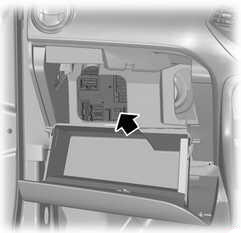
Passenger Compartment Fuse Box
It is located behind the glove box in the instrument panel. Open the glove box and empty, press the side clips of the glove box inwards and swivel the box further down.
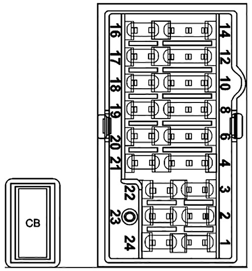
| № | A | Circuits Protected |
|---|---|---|
| 1 | 10 | Audio unit (without SYNC) |
| 2 | 30 | - |
| 3 | 20 | - |
| 4 | 7.5 | Power windows logic (one touch up/down), Power mirrors |
| 6 | 10 | Climate control module, SYNC module, Multi function display, Integrated control panel, GPS module, USB charger (without SYNC) |
| 8 | 7.5 | Instrument cluster, Datalink Gateway module (with SYNC) |
| 10 | 5 | Climate control module (without A/C), In-car temperature sensor (with EATC), Electric power assist steering |
| 12 | 10 | Airbag control module, Passenger Airbag desactivation switch, Windshield washer pump |
| 14 | - | - |
| 16 | 30 | Body control module ignition relay |
| 17 | 20 | Radio supply battery |
| 18 | 10 | Datalink Gateway module (with SYNC) |
| 19 | 10 | Ignition switch |
| 20 | - | - |
| 21 | 10 | - |
| 22 | 10 | Rear parking aid module |
| 23 | 20 | Power door locks relay |
| 24 | 25 | - |
| CB01 | 30 | Circuit Breaker: Power windows |
Advertisements
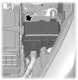
Engine Compartment Fuse Box
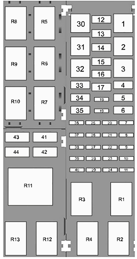
| № | A | Circuits Protected |
|---|---|---|
| 1 | 40 | Blower motor |
| 2 | - | - |
| 3 | - | - |
| 4 | 30 | Vehicles four and five doors without heated seat, Vehicle five doors with heated seat |
| 4 | 40 | Vehicle four doors with heated seat |
| 5 | 30 | Starter relay |
| 6 | - | - |
| 7 | - | - |
| 8 | 5 | Power control module relay coil, Fuel pump relay coil, Ignition relay coil |
| 9 | 10 | AC compressor |
| 10 | - | - |
| 11 | - | - |
| 12 | - | - |
| 13 | - | - |
| 14 | - | - |
| 15 | - | - |
| 16 | - | - |
| 17 | 20 | Cigar Lighter |
| 18 | 10 | Horn |
| 19 | 7.5 | Heated Mirrors |
| 20 | 20 | Powertrain control module |
| 21 | 20 | HEGO sensor, CMS sensor, Purge valve, Variable camshaft timing |
| 22 | 5 | A/C relay coil, Cooling fan relay coil |
| 23 | 15 | Ignition coil |
| 24 | - | - |
| 25 | 5 | Wiper relay coil |
| 26 | 5 | Heated backlite relay coil |
| 27 | 10 | Anti-lock brake system module, Headlamp leveller |
| 28 | 10 | Powertrain control module |
| 29 | - | - |
| 30 | - | - |
| 31 | 40 | Anti-lock brake system |
| 32 | - | - |
| 33 | 30 | Trailer tow |
| 34 | 20 | Heated seats |
| 35 | 30 | Cooling Fan |
| 36 | - | - |
| 37 | 20 | Fuel pump, Fuel injectors |
| 38 | 20 | Electronic stability control module |
| 39 | 10 | Brake switch |
| 40 | 20 | Horn relays |
| 41 | 20 | Front wiper motor |
| 42 | 15 | Rear wiper motor |
| 43 | 10 | Horn |
| 44 | 10 | Daytime running light |
| R1 | Powertrain control module and loads | |
| R2 | Wiper | |
| R3 | Ignition loads | |
| R4 | Daytime running light | |
| R5 | Starter motor | |
| R6 | AC compressor | |
| R7 | Heated backlite | |
| R8 | Heated seats | |
| R9 | Horn (Body control module) | |
| R10 | Cooling fan | |
| R11 | - | |
| R12 | Blower motor | |
| R13 | Fuel pump | |
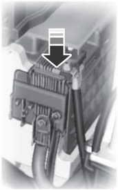
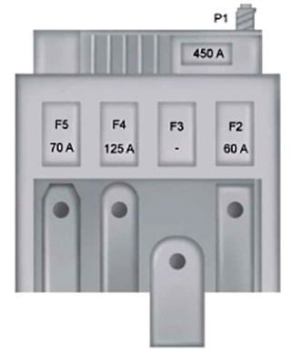
Battery Fuse Box
This fuse box in attached to the battery positive terminal.
| № | A | Circuits Protected |
|---|---|---|
| 1 | 450 | Starter motor Alternator |
| 2 | 60 | Electrical power assisted steering. |
| 3 | - | Engine junction box |
| 4 | 125 | Body control module |
| 5 | 70 | - |
Advertisements