
Advertisements
Fuse box diagram (fuse layout), location and assignment of fuses and relays Ford Galaxy and S-Max (2015, 2016, 2017, 2018).

Checking and Replacing Fuses
Fuses and circuit breakers protect your vehicle’s electrical system from overloading. If electrical parts in your vehicle are not working, the system may have been overloaded and blown a fuse or tripped a circuit breaker. Before you replace or repair any electrical parts, check the appropriate fuses or circuit breakers.
To check a fuse, look at the silver-colored band inside the fuse. If the band is broken or melted, replace the fuse.
Notice
- Before replacing fuses check that the key has been removed from the ignition and that all the services are switched off and/or disengaged.
- Always disconnect the battery before servicing high current fuses.
- Always replace a fuse with one that has the specified amperage rating. Using a fuse with a higher amperage rating can cause severe wire damage and could start a fire.
- Never replace a broken fuse with anything other than a new fuse. Use always an intact fuse of the same color.
- If a fuse blows again contact a qualified service center.
Instrument Panel Fuse Box Diagram
The fuse panel is located under the instrument panel to the left of the steering column.
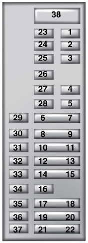
| № | A | Protected components |
|---|---|---|
| 1 | 10 | Lighting (ambient, glove box, vanity, dome, liftgate) |
| 2 | 7.5 | Memory seats, lumbar, power mirror |
| 3 | 20 | Driver door unlock |
| 4 | 5 | Aftermarket electronic trailer brake on/off switch |
| 5 | 20 | Ignition switch |
| Push-button ignition switch | ||
| 6 | 10 | Heated seat relay coil |
| 7 | 10 | Not used (spare) |
| 8 | 10 | Not used (spare) |
| 9 | 10 | Not used (spare) |
| 10 | 5 | Keypad |
| Power liftgate module | ||
| 11 | 5 | Not used |
| 12 | 7.5 | Climate control |
| 13 | 7.5 | Steering wheel column lock |
| Cluster | ||
| Datalink logic | ||
| 14 | 10 | Not used |
| 15 | 10 | Datalink gateway module |
| 16 | 15 | Child lock |
| Liftgate release | ||
| 17 | 5 | Not used (spare) |
| 18 | 5 | Ignition |
| Push button stop start switch | ||
| 19 | 7.5 | Passenger airbag disabled indicator |
| Transmission range indicator | ||
| 20 | 7.5 | Not used (spare) |
| 21 | 5 | Humidity and in-car temperature sensor |
| Blind spot information system | ||
| Rear video camera | ||
| Adaptive cruise control | ||
| 22 | 5 | Occupant classification sensor |
| 23 | 10 | Delayed accessory (power inverter logic, moonroof logic) |
| 24 | 20 | Central lock unlock |
| 25 | 30 | Driver door (window, mirror) |
| 26 | 30 | Front passenger door (window, mirror) |
| 27 | 30 | Moonroof |
| 28 | 20 | Amplifier |
| 29 | 30 | Rear driver side door (window) |
| 30 | 30 | Rear passenger side door (window) |
| 31 | 15 | Not used (spare) |
| 32 | 10 | Global positioning system |
| Display | ||
| Voice control | ||
| Adaptive cruise control | ||
| Radio frequency receiver | ||
| 33 | 20 | Radio |
| 34 | 30 | Run-start bus (fuse 19,20,21,22,35,36, 37, circuit breaker) |
| 35 | 5 | Restraints control module |
| 36 | 15 | Auto-dimming rearview mirror |
| Heated seat | ||
| All-wheel drive | ||
| 37 | 15 | Voltage stability module logic power |
| 38 | 30 | Not used (spare) |
Advertisements
Engine Compartment Fuse Box Diagram
The power distribution box is located in the engine compartment. It has high-current fuses that protect your vehicle’s main electrical systems from overloads.
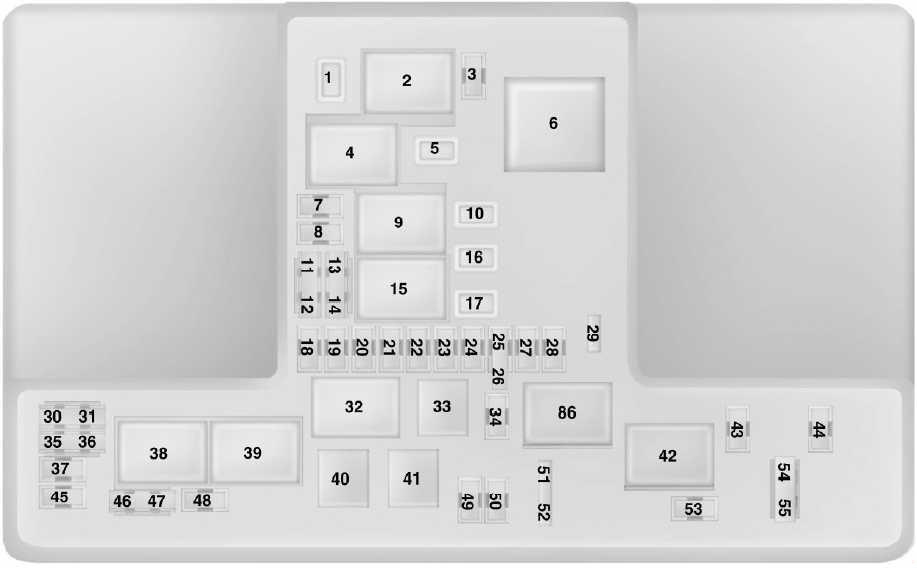
| № | A | Protected components |
|---|---|---|
| 1 | 25 | Wiper motor |
| 3 | 15 | Rear wiper |
| Rain sensor | ||
| 5 | 20 | Power point 3 - Back of console |
| 7 | 20 | Powertrain control module - vehicle power 1 |
| 8 | 20 | Powertrain control module - vehicle power 2 |
| 10 | 20 | Power point 1 - driver front |
| 11 | 15 | Powertrain control module - vehicle power 4 |
| 12 | 15 | Powertrain control module - vehicle power 3 |
| 13 | 10 | Not used (spare) |
| 14 | 10 | Not used (spare) |
| 16 | 20 | Power point 2 - console |
| 17 | 20 | Power point 4 - luggage compartment |
| 18 | 10 | Not used (spare) |
| 19 | 10 | Run-start electronic power assist steering |
| 20 | 10 | Run/start lighting |
| 21 | 15 | Run/start transmission control |
| Transmission oil pump start/stop | ||
| 22 | 10 | Air conditioner clutch solenoid |
| 23 | 15 | Run-start |
| Blind spot information system | ||
| Rear view camera | ||
| Adaptive cruise control | ||
| Heads-up display | ||
| Voltage stability module | ||
| 24 | 10 | Run-start |
| 25 | 10 | Run-start anti-lock brake system |
| 26 | 10 | Run-start powertrain control module |
| 27 | - | Not used |
| 28 | 10 | Rear washer pump |
| 29 | - | Not used |
| 30 | - | Not used |
| 31 | - | Not used |
| 34 | 15 | Electric steering column lock |
| 35 | - | Not used |
| 36 | - | Not used |
| 37 | - | Not used |
| 43 | 10 | Not used (spare) |
| 44 | 5 | Heated washer nozzle |
| 45 | - | Not used |
| 46 | 10 | Alternator sensor |
| 47 | 10 | Brake on/off switch |
| 48 | 20 | Horn |
| 49 | 20 | Diesel fuel heater |
| 50 | 10 | Power transfer unit fan |
| 51 | - | Not used |
| 52 | - | Not used |
| 53 | 10 | Power seats |
| 54 | 5 | Fuel operated heater |
| 55 | 5 | Fuel operated heater |
| 2 | Starter relay | |
| 4 | Blower motor relay | |
| 6 | Auxiliary heater #2 relay | |
| 9 | Powertrain control module relay | |
| 15 | Run-start relay | |
| 32 | Electronic fan 1 relay | |
| 33 | A/C clutch relay | |
| 38 | Electronic fan 2 relay | |
| 39 | Electric fan 2 and 3 relay | |
| 40 | Headlamp washer relay | |
| 41 | Horn relay | |
| 42 | Fuel pump relay | |
| 86 | Not used | |
Advertisements
Bottom of the Power Distribution Box
There are fuses located on the bottom of the fuse box.
To access the bottom of the fuse box, do the following:
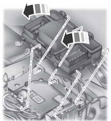
- Release the two latches, located on both sides of the fuse box.
- Raise the inboard side of the fuse box from the cradle.
- Move the fuse box toward the center of the engine compartment.
- Pivot the outboard side of the fuse box to access the bottom side.
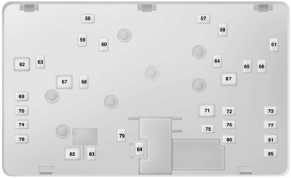
| № | A | Protected components |
|---|---|---|
| 56 | 20 | Headlamp washer |
| 57 | 20 | Diesel vaporizer |
| 58 | 30 | Fuel pump feed |
| 59 | 40 | 600W Electronic fan 3 |
| 60 | 40 | 600W Electronic fan 1 |
| 61 | 40 | Left hand side windshield defrost |
| 62 | 50 | Body control module 1 |
| 64 | 30 | Auxiliary heater #3 |
| 65 | 20 | Front heated seat |
| 66 | 40 | Right hand side windshield defrost |
| 67 | 50 | Body control module 2 |
| 68 | 40 | Heated rear window |
| 69 | 30 | Anti-lock brake system valves |
| 70 | 30 | Passenger seat |
| 71 | 60 | Auxiliary heater #2 |
| 72 | 30 | Rear power seats |
| 73 | 20 | Rear heated seats |
| 74 | 30 | Driver seat module |
| 75 | 30 | Auxiliary heater #1 |
| 76 | 20 | Transmission oil pump |
| 77 | 30 | Climate control seat module |
| 78 | 40 | Trailer tow module |
| 79 | 40 | Blower motor |
| 80 | 40 | Power liftgate module |
| 81 | 40 | 220 volt inverter |
| 82 | 60 | Anti-lock brake system pump |
| 83 | 25 | Wiper motor #1 |
| 84 | 30 | Starter solenoid |
| 85 | 20 | Fuel fire heater |
| 87 | 50 | Auxiliary blower motor |
Advertisements