
Advertisements
Fuse box diagram (fuse layout), location and assignment of fuses and relays Ford Freestar (2003, 2004, 2005, 2006, 2007).

Checking and Replacing Fuses
Fuses and circuit breakers protect your vehicle’s electrical system from overloading. If electrical parts in your vehicle are not working, the system may have been overloaded and blown a fuse or tripped a circuit breaker. Before you replace or repair any electrical parts, check the appropriate fuses or circuit breakers.
To check a fuse, look at the silver-colored band inside the fuse. If the band is broken or melted, replace the fuse.
Notice
- Before replacing fuses check that the key has been removed from the ignition and that all the services are switched off and/or disengaged.
- Always disconnect the battery before servicing high current fuses.
- Always replace a fuse with one that has the specified amperage rating. Using a fuse with a higher amperage rating can cause severe wire damage and could start a fire.
- Never replace a broken fuse with anything other than a new fuse. Use always an intact fuse of the same color.
- If a fuse blows again contact a qualified service center.
Passenger Compartment Fuse Box Diagram
The fuse panel is located below and to the left of the steering wheel by the brake pedal. To remove the fuse panel cover, pull up on the latch on the right or left side of the cover.
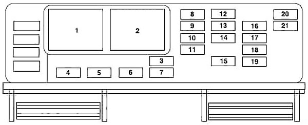
| № | A | Fused component |
|---|---|---|
| 3 | 10 | Front wiper motor Run feed |
| 4 | 5 | B+ feed to outside mirrors |
| 5 | 20 | Vent window power feed/Radio feed |
| 6 | 5 | Driver door switch illumination/Passenger door switch illumination |
| 7 | 10 | Rear wiper Run feed |
| 8 | 10 | Cluster/Electronic Automatic Temperature Control (EATC) B+ feed, DVD |
| 9 | 10 | Passive Anti-theft System (PATS) LED feed |
| 10 | 5 | Auxiliary radio |
| 11 | 5 | Auxiliary climate control system/Power Liftgate Module/Left and right power sliding door module/Data Link Connector (DLC)/Clock B+ feeds |
| 12 | 5 | Brake-Shift Interlock (BSI) Run feed, Climate control system Run feed |
| 13 | 5 | Compass/Driver heated seat/Passenger heated seats/Reverse sensing system/Power Liftgate Module/Power sliding door Run feeds |
| 14 | 5 | Underhood fuse box Rim feed, Front blower Run feed |
| 15 | 10 | Brake On-Off (BOO) switch B+ |
| 16 | 5 | Steering angle/Cluster/Power sliding door and power liftgate inhibit LED/Electrochromatic mirror Run/Start/Tire Pressure Monitoring System (TPMS) |
| 17 | 10 | Restraint Control Module (RCM)/Passenger Air bag Disable Indicator (PADI)/Passenger Occupant Detection System (PODS) Run/Start |
| 18 | 10 | Anti-lock Brake System (ABS) module/Brake pressure switch/Speed control Run/Start |
| 19 | 5 | PATS/Cluster/Air bag LED/Powertrain Control Module (PCM) relay Run/Start |
| 20 | 10 | Liftgate Start feed, Radio Start feed |
| 21 | 10 | Starter relay power START |
| 1 | Accessory delay relay 1 | |
| 2 | Accessory delay relay 2 | |
Advertisements
Engine Compartment Fuse Box Diagram
The power distribution box is located in the engine compartment. It contains high-current fuses that protect your vehicle’s main electrical systems from overloads.
The cover for the power distribution box can be removed by releasing the tab on the back left corner of the cover, then pulling the cover up.
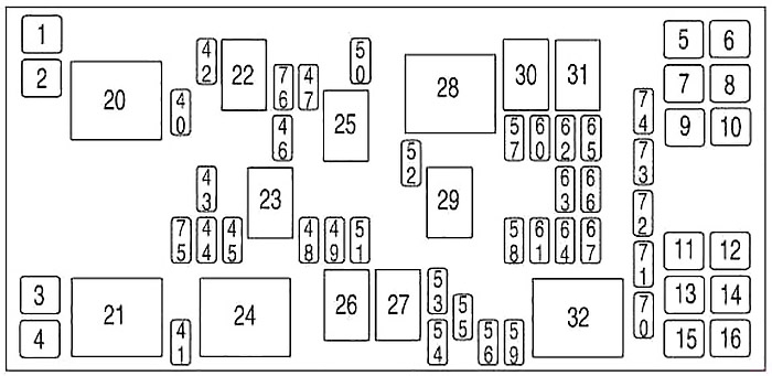
| № | A | Fused component |
|---|---|---|
| 1 | — | Not used |
| 2 | 30 | Right cooling fan |
| 3 | 30 | Left cooling fan |
| 4 | 30 | Starter solenoid |
| 5 | 30 | Right-hand power sliding door |
| 6 | 30 | SJB accessory #2 (driver power window) |
| 7 | 30 | Auxiliary blower motor |
| 8 | 40 | Anti-lock Brake System (ABS) #2 (coil power) |
| 9 | 30 | Power liftgate |
| 10 | 30 | SJB accessory #1 (passenger window, radio, vent windows') |
| 11 | 30 | Left, power seat/heated seat |
| 12 | 40 | ABS #1 (pump motor) |
| 13 | 40 | Rear defroster |
| 14 | 30 | Front climate control system blower motor |
| 15 | 30 | Right power seat/heated seat |
| 16 | 30 | Left-hand power sliding door |
| 40 | 15 | Engine #1 (A/C relay coil, IMRC, HEGO sensors, Canister purge, Transmission module, Canister vent) |
| 41 | 25 | Horn |
| 42 | 10 | A/C clutch |
| 43 | 15 | Engine #2 (Cooling fan relays, Injectors, PCM, MAF sensor, LAC, Ignition coil, ESM) |
| 44 | 10 | Heated PCV |
| 45 | 15 | High beams |
| 46 | 20 | Trailer stop/turn lamps |
| 47 | 15 | Fuel pump, Fuel pump shut-off switch |
| 48 | — | Not used |
| 49 | 10 | PCM KAP, Canister vent |
| 50 | 10 | Alternator |
| 51 | 10 | Adjustable pedals (non-memory) or memory module |
| 52 | 20 | Trailer tow park lamps |
| 53 | 10 | Heated mirrors |
| 54 | 30 | Front wiper motor |
| 55 | 25 | Rear wiper motor |
| 56 | 30 | Premium sound radio |
| 57 | 20 | Cigar lighter |
| 58 | 30 | SJB #1 - Center High-Mounted Stop Lamp (CHMSL), License plate lamps, OBD II, Dome lamp, Auxiliary blend doors, Switch illumination (feeds F-8, F-9, F-10 and F-ll) |
| 59 | 20 | Radio (non-premium) |
| 60 | 30 | SJB #4 - Back-up lamps, Door locks, Theft sounder |
| 61 | 20 | 3rd row power point |
| 62 | 30 | SJB #3 - Right cornering/auxiliary lamps, Right low beam, Left front park/turn lamps, Left rear park/stop/turn lamps, Instrument panel courtesy lamps, Step well lamps, Left signal mirror, Clock, Cluster, Message center (SJB F-15), Switch illumination for: overhead console, DVD/Rear climate control system, Headlamp switch illumination, Climate control illumination |
| 63 | 20 | Instrument panel power point, Cigar lighter |
| 64 | 20 | Ignition switch #1 feed |
| 65 | 30 | SJB #2 - Left cornering/auxiliary lamps, Left low beam, Right front park/turn lamps, Right rear park/stop/tum lamps, Puddle lamps, Mirror signals, Visors, 2nd and 3rd row lamps, Cargo lamp, Defroster indicator |
| 66 | 20 | 2nd and 3rd row seat power points |
| 67 | 20 | Ignition switch #2 feed |
| 70 | — | Not used |
| 71 | — | Not used |
| 72 | — | Not used |
| 73 | — | Not used |
| 74 | — | Not used |
| 20 | Powertrain Control Module (PCM) power | |
| 21 | Horn | |
| 22 | A/C clutch | |
| 23 | High beams | |
| 24 | Starter | |
| 25 | Fuel pump | |
| 26 | Not used | |
| 27 | Not used | |
| 28 | Auxiliary blower | |
| 29 | Trailer park lamps | |
| 30 | Left trailer stop/turn lamps | |
| 31 | Right trailer stop/tum lamps | |
| 32 | Rear defroster | |
| 75 | PCM | |
| 76 | A/C clutch | |
Auxiliary relay box
The relay box is located in the engine compartment by the radiator and contains fuses and relays for cooling fans.
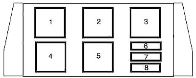
| № | A | Fused component |
|---|---|---|
| 6 | 40 | Right-hand cooling fan motor (Vehicles with trailer tow package only) |
| 7 | 15 | Low-speed cooling fan circuit breaker (Vehicles with trailer tow package only) |
| 8 | 40 | Left-hand cooling fan motor (Vehicles with trailer tow package) |
| 10 | Low-speed cooling fan circuit breaker (Vehicles without trailer tow package) | |
| 1 | Cooling fan relay | |
| 2 | Cooling fan relay | |
| 3 | Cooling fan relay | |
| 4 | Cooling fan relay | |
| 5 | Cooling fan relay | |
Advertisements