
Advertisements
Fuse box diagram (fuse layout), location and assignment of fuses and relays Ford F250, F350, F450, F550 (2017, 2018, 2019).

Checking and Replacing Fuses
Fuses and circuit breakers protect your vehicle’s electrical system from overloading. If electrical parts in your vehicle are not working, the system may have been overloaded and blown a fuse or tripped a circuit breaker. Before you replace or repair any electrical parts, check the appropriate fuses or circuit breakers.
To check a fuse, look at the silver-colored band inside the fuse. If the band is broken or melted, replace the fuse.
Notice
- Before replacing fuses check that the key has been removed from the ignition and that all the services are switched off and/or disengaged.
- Always disconnect the battery before servicing high current fuses.
- Always replace a fuse with one that has the specified amperage rating. Using a fuse with a higher amperage rating can cause severe wire damage and could start a fire.
- Never replace a broken fuse with anything other than a new fuse. Use always an intact fuse of the same color.
- If a fuse blows again contact a qualified service center.
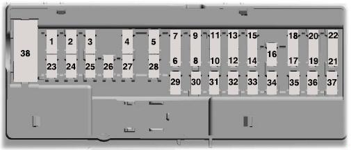
Passenger Compartment Fuse Box Diagram
The fuse panel is on the right-hand side of the passenger footwell behind a trim panel. Pull the trim panel toward you and swing it away from the side to remove. To reinstall it, line up the tabs with the grooves on the panel, and then push it shut.
Note: It may be easier to access the fuse panel if you remove the finish trim piece.
| № | A | Protected components |
|---|---|---|
| 1 | - | - |
| 2 | 7.5 | Memory seat switch (lumbar power) |
| 3 | 20 | Driver door unlock relay |
| 4 | 5 | Aftermarket electronic brake controller, Trailer brake controller Brake On/Off, Customer access circuits |
| 5 | - | - |
| 6 | - | - |
| 7 | - | - |
| 8 | - | - |
| 9 | 10 | Brake On/Off / Pressure Switch |
| 10 | - | - |
| 11 | 5 | Combined sense security module |
| 12 | 7.5 | Front climate control module |
| 13 | 7.5 | Instrument cluster, Smart data link, Steering column control module |
| 14 | 10 | Extended power restraints module |
| 15 | 10 | Smart datalink connector power |
| 16 | 10 | Tailgate release solenoid |
| 17 | 5 | Head-up display |
| 18 | 5 | Push button ignition switch, Ignition switch, Key inhibit |
| 19 | 7.5 | Transmission control switch (tow/haul), Select Shift switch |
| 20 | 7.5 | Active front steering module |
| 21 | 5 | Head-up display, Humidity sensor |
| 22 | 5 | Upfitter switch, Run/Start, PTO relays |
| 23 | 10 | Accessory delay, Power windows, Moonroof, Power folding mirrors relay, Inverter, Window/moon roof switch illumination |
| 24 | 20 | Central locking system relay |
| 25 | 30 | Left-hand front smart window motor, Door zone module |
| 26 | 30 | Right-hand front smart window motor, Door zone module |
| 27 | 30 | Moon roof |
| 28 | 20 | Sony amplifier -10 channel |
| 29 | - | - |
| 30 | - | - |
| 31 | 15 | Adjustable pedals switch |
| 32 | 10 | SYNC, GPS module, Display, Radio frequency receiver |
| 33 | 20 | Radio |
| 34 | 30 | Run-start relay |
| 35 | 5 | Extended power restraints module |
| 36 | 15 | Lane keeping system, Automatic high beam control, Auto-dimming mirrors, Rear heated seats, Camera module |
| 37 | 20 | Heated steering wheel |
| 38 | 30 | Circuit breaker: Rear power window switch |
Advertisements
Engine Compartment Fuse Box Diagram
The power distribution box is located in the engine compartment. The power distribution box contains high-current fuses that protect your vehicle’s main electrical systems from overloads.

| № | A | Protected components |
|---|---|---|
| 1 | 20 | Powertrain control module |
| 2 | 20 | Emissions (MIL) |
| 3 | 20 | Cooling fan, A/C compressor, Engine brake |
| 4 | 20 | Noise suppression cap, Mass air flow sensor, Emissions, Glow plugs, Urea |
| 5 | 15 | Compressed natural gas fuel control module |
| 6 | - | - |
| 7 | - | - |
| 8 | - | - |
| 9 | - | - |
| 10 | 10 | Heated exterior mirrors |
| 12 | 40 | Heated rear window |
| 13 | - | - |
| 15 | 20 | Horn |
| 16 | 10 | A/C clutch relay power |
| 22 | 20 | Auxiliary power point #5 (rear console), Run-start |
| 23 | - | - |
| 26 | - | - |
| 27 | 30 | Trailer tow battery charge relay |
| 30 | 10 | 4x4 module |
| 31 | 5 | Adaptive cruise control, Run-start |
| 32 | 5 | Anti-lock brake system module, Run-start |
| 33 | 10 | Powertrain control module (ISPR), Run-start, Engine control module, Transmission control module |
| 34 | 10 | Blind spot information system, Run-start, Front camera, Rear camera |
| 35 | - | - |
| 41 | 25 | Glow plugs |
| 42 | 40 | Trailer tow lighting module |
| 43 | 40 | Front blower motor |
| 44 | 50 | Voltage quality module, Body control module |
| 45 | 60 | Active front steering |
| 46 | 50 | Supplemental air heater bank #2 |
| 47 | 50 | Cooling fan, Supplemental air heater bank #3 |
| 48 | 50 | Body control module RP1 bus |
| 49 | 60 | Inverter |
| 50 | 50 | Body control module RP2 bus |
| 51 | 60 | Body control module B+ feed |
| 52 | 60 | Anti-lock brake system pump |
| 53 | 50 | Supplemental air heater bank #1 |
| 54 | 30 | Trailer brake control module |
| 55 | 30 | Climate controlled seat module |
| 56 | 40 | Auxiliary lighting module |
| 57 | 30 | Power running boards |
| 58 | 30 | Compressed natural gas fuel control module relay |
| 59 | 30 | Anti-lock brake system valve |
| 60 | - | - |
| 61 | 30 | Driver power seat |
| 62 | 20 | Auxiliary power point #1 (instrument panel) |
| 63 | 30 | Starter motor |
| 64 | 20 | Auxiliary power point #2 |
| 65 | 30 | Trailer tow lighting module |
| 66 | 20 | Auxiliary power point #3 (center console) |
| 67 | 30 | Passenger power seat |
| 68 | 20 | Auxiliary power point #4 (rear media bin) |
| 69 | 2 0 | 4x4 module |
| 70 | - | - |
| 71 | - | - |
| 72 | 30 | Trailer tow left hand/right hand stop/turn |
| 73 | - | - |
| 74 | - | - |
| 75 | 30 | Fuel pump |
| 76 | - | - |
| 77 | 30 | Wiper motor |
| 78 | - | - |
| 79 | 30 | Power sliding rear window |
| 80 | 25 | 4x4 module |
| 81 | 10 | 4x4 solenoid |
| 82 | 10 | Power telescoping mirrors |
| 83 | 20 | Rear heated seats |
| 84 | 10 | Trailer tow backup lamps |
| 85 | - | - |
| 86 | - | - |
| 87 | - | - |
| 88 | 10 | Multi contour seats |
| 89 | - | - |
| 90 | 10 | Spot light module |
| 91 | 10 | Upfitter interface module |
| 92 | - | - |
| 93 | - | - |
| 94 | 10 | Transmission control module |
| 95 | 10 | Powertrain control module keep alive power |
| 96 | 5 | Rain sensor |
| 97 | - | - |
| 98 | 10 | Alternator sense |
| 99 | 30 | Trailer tow parking lamps |
| 11 | CNG relay | |
| 14 | Powertrain control module relay | |
| 17 | Rear heated window and heated mirrors relay | |
| 18 | - | |
| 19 | - | |
| 20 | Supplemental air heater bank #1 relay | |
| 21 | - | |
| 24 | Cooling fan relay, | |
| Supplemental air heater bank #3 relay | ||
| 25 | Glow plug module power relay | |
| 29 | Run-start relay | |
| 36 | Blower motor relay | |
| 37 | Trailer tow battery charge relay | |
| 38 | A/C compressor clutch relay | |
| 39 | Horn relay | |
| 40 | Supplemental air heater bank #2 relay | |
Advertisements