
Advertisements
Fuse box diagram (fuse layout), location, and assignment of fuses and relays Ford F150 / F150 Raptor (2021, 2022).

Checking and Replacing Fuses
If electrical components in the vehicle are not working, a fuse may have blown. Blown fuses are identified by a broken wire within the fuse. Check the appropriate fuses before replacing any electrical components.
Note
- Before replacing a fuse check that the key has been removed from the ignition and that all the services are switched off and/or disengaged.
- Always replace a fuse with one that has the specified amperage rating. Using a fuse with a higher amperage rating can cause severe wire damage and could start a fire.
- If a fuse blows again contact a qualified service center.
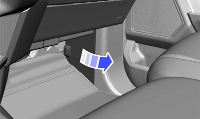
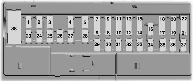
Passenger Compartment Fuse Box Diagram
| № | A | Protected Circuit |
|---|---|---|
| 1 | - | - |
| 2 | 10 | Delayed Accessory Feed |
| 3 | 7.5 | Wireless Charger |
| 4 | 20 | - |
| 5 | - | - |
| 6 | 10 | Driver Power Window Switch |
| 7 | 10 | Gear Shift Module |
| 8 | 5 | Cell Phone Passport Module |
| 9 | 5 | Combined Sensor Module |
| 10 | - | - |
| 11 | - | - |
| 12 | 7.5 | Enhanced Central Gateway, Climate Control |
| 13 | 7.5 | Instrument Cluster, Steering Column Control Module |
| 14 | 15 | - |
| 15 | 15 | Integrated Control Panel, SYNC |
| 16 | - | - |
| 17 | 7.5 | Headlamp Control Module |
| 18 | 7.5 | - |
| 19 | 5 | Headlamp Switch |
| 20 | 5 | Passive Start, Ignition Switch, Key Inhibit Solenoid |
| 21 | 5 | Trailer Brake Switch |
| 22 | 5 | - |
| 23 | 30 | Driver Door Control Module |
| 24 | 30 | Moonroof |
| 25 | 20 | - |
| 26 | 30 | Passenger Door Control Module |
| 27 | 30 | - |
| 28 | 30 | Amplifier |
| 29 | 15 | 12 Inch Display, Adjustable Pedals |
| 30 | 5 | - |
| 31 | 10 | RF Receiver, Driver Monitor, Terrain Management Switch |
| 32 | 20 | Audio Control Module |
| 33 | - | - |
| 34 | 30 | Run/Start Relay |
| 35 | 5 | 400 Watt Inverter Run/Start |
| 36 | 15 | Auto-Dimming Interior Mirror, Rear Heat Seat Run/Start, Adaptive Front Steering Run/Start, Heated Wheel (Vehicles Without Adaptive Front Steering) |
| 37 | 20 | Advanced Driver-Assistance Systems |
| 38 | 30 | Rear Power Windows (Circuit Breaker) |
Advertisements
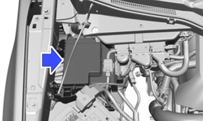
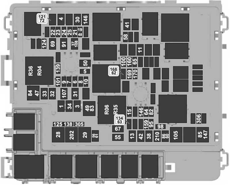
Engine Compartment Fuse Box Diagram
| № | A | Description |
|---|---|---|
| 1 | 40 | Body Control Module - Battery Power In Feed 1 |
| 3 | 40 | Body Control Module - Battery Power In Feed 2 |
| 4 | 30 | Fuel Pump |
| 5 | 5 | Powertrain Control Module Coil |
| 6 | 25 | Powertrain Control Module Power |
| 7 | 20 | Powertrain Control Module Power |
| 8 | 10 | Powertrain Control Module Power |
| 20 | Hybrid: Powertrain Control Module Power | |
| 9 | 20 | Powertrain Control Module Power |
| 10 | 20 | Diesel: Powertrain Control Module Power |
| 11 | 30 | Starter Motor |
| 13 | 40 | Blower Motor |
| 15 | 25 | Horn |
| 19 | 20 | Snow Plow Switch (Gasoline), Rear Heated Seats |
| 21 | 10 | Headlamp Run/Start Feed |
| 22 | 10 | Electronic Power Assist Steering |
| 23 | 10 | Electric Brake Boost |
| 24 | 10 | Gasoline, Hybrid: Powertrain Control Module |
| 10 | Diesel: Transmission Control Module, Glow Plug Control Module | |
| 25 | 10 | Center High-Mounted Stop, Lamp Camera, Trailer Camera, 2 KW Inverter, 24 V Alternator - Run/Start Feed, Analog Rear Video Camera |
| 28 | 50 | Electric Brake Boost |
| 29 | 50 | Electric Brake Boost |
| 30 | 40 | Driver Power Seat |
| 31 | 30 | Passenger Power Seat |
| 32 | 20 | Auxiliary Power Point |
| 33 | 20 | Auxiliary Power Point, USB Smart Charger |
| 34 | 20 | Auxiliary Power Point |
| 35 | 30 | Tailgate Module |
| 36 | 40 | Climate Controlled Seat Module, Power Running Boards |
| 41 | 25 | Power Sliding Back Window |
| 42 | 30 | Trailer Brake Control Module |
| 47 | 50 | except Diesel: Cooling Fan |
| 48 | 20 | Raptor, Tremor: Rear Heated Seats |
| 49 | 50 | except Diesel: Cooling Fan |
| 50 | 40 | Gasoline, Hybrid: Heated Backlight |
| 55 | 30 | Trailer Tow Park Lamps |
| 56 | 20 | Trailer Tow Stop and Turn Lamps (4-pin Connector) |
| 58 | 10 | Trailer Tow Backup Lamps |
| 60 | 15 | Raptor, Tremor: Upfitter 1 Relay |
| 61 | 15 | Raptor, Tremor: Upfitter 2 Relay |
| 62 | 10 | Raptor, Tremor: Upfitter 3 Relay |
| 63 | 10 | Raptor, Tremor: Upfitter 4 Relay |
| 64 | 25 | Four-Wheel Drive |
| 65 | 15 | Transmission Control Module |
| 67 | 20 | Transmission Run/Start |
| 69 | 30 | Left-Hand Windshield Wiper |
| 82 | 25 | Four-Wheel Drive |
| 83 | 50 | Diesel: Supplemental Heater |
| 84 | 50 | Diesel: Supplemental Heater |
| 85 | 50 | Diesel: Supplemental Heater |
| 86 | 25 | Diesel: Selective Catalytic Reduction System |
| 91 | 20 | Trailer Tow Light Module |
| 95 | 15 | Hybrid: Powertrain Control Module Power |
| 98 | 10 | Hybrid: Powertrain Control Module Power, Coolant Pumps |
| 100 | 15 | Left-Hand Headlamps |
| 101 | 15 | Right-Hand Headlamps |
| 105 | 50 | Active Front Steering |
| 107 | 30 | Trailer Tow Battery Charge |
| 108 | 15 | Police: Spot Lamps |
| 121 | 30 | Diesel: Fuel Filter Heater |
| 124 | 5 | Rain Sensor Module |
| 125 | 10 | USB Smart Charger |
| 134 | 25 | except Raptor, Tremor: Multi-Contour Seats Relay |
| 138 | 10 | Tailgate Release |
| 139 | 5 | USB Smart Charger |
| 146 | 15 | Hybrid: Traction Battery Control Module |
| 147 | 40 | Raptor, Tremor: Change Air Cooler Fan Relay |
| 159 | 5 | Hybrid: DC/DC Power |
| 160 | 10 | Smart Data Link Control |
| 168 | 15 | Hybrid: Traction Battery Control Module |
| 169 | 10 | Hybrid: Motor Electric Cool Pump |
| 170 | 10 | Hybrid: Pedestrian Alert Control Module, Traction Battery Control Module, Electric Motor Cool Pump |
| 202 | 60 | Body Control Module B+. |
| 210 | 30 | Body Control Module Start Stop |
| 305 | 5 | Raptor, Tremor: Upfitter 5 Relay |
| 306 | 5 | Raptor, Tremor: Upfitter 6 Relay |
| R04 | Electronic Fan Relay №: 1 | |
| R06 | Electronic Fan Relay №: 3 | |
| R35 | Supplemental Heater | |
| R36 | Supplemental Heater | |
Advertisements