
Advertisements
Fuse box diagram (fuse layout), location and assignment of fuses and relays Ford Crown Victoria “Crown Vic” (1998, 1999, 2000, 2001, 2002).
Checking and Replacing Fuses
Fuses and circuit breakers protect your vehicle’s electrical system from overloading. If electrical parts in your vehicle are not working, the system may have been overloaded and blown a fuse or tripped a circuit breaker. Before you replace or repair any electrical parts, check the appropriate fuses or circuit breakers.
If electrical components in the vehicle are not working, a fuse may have blown. Blown fuses are identified by a broken wire within the fuse. Check the appropriate fuses before replacing any electrical components.
Note
- Before replacing a fuse check that the key has been removed from the ignition and that all the services are switched off and/or disengaged.
- Do not repair fuses and never replace a blown fuse with one that has a higher amp rating. This can cause damage to the electrical system and fire.
- Never replace a broken fuse with anything other than a new fuse. Use always an intact fuse of the same color.
- If a fuse blows again contact a qualified service center.
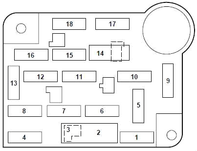
Passenger Compartment Fuse Box
The fuse panel is located below and to the left of the steering wheel by the brake pedal. Remove the panel cover to access the fuses.
Diagram 1998-2000
| № | A | Protected components |
|---|---|---|
| 1 | 15 | Brake Pedal Position (BPP) Switch, Multi-Function Switch, Speed Control |
| 2 | 30 | Wiper Control Module, Windshield Wiper Motor |
| 3 | — | - |
| 4 | 15 | Lighting Control Module, Main Light Switch |
| 5 | 15 | Backup Lamps, Variable Assist Power Steering (MAPS), Turn Signals, Air Suspension, Daytime Running Lamps, Electronic Day/Night Mirror, Shift Lock, EATC, Speed Chime Warning |
| 6 | 15 | Speed Control, Main Light Switch, Lighting Control Module, Clock, Police Power Relay |
| 7 | 25 | Powertrain Control Module (PCM) Power Diode, Ignition Coils |
| 8 | 15 | Lighting Control Module, Power Mirrors, PATS Module, Keyless Entry, Clock Memory, Electronic Automatic Temperature Control (EATC), Power Windows, Police Spot Light, SecuriLock |
| 9 | 30 | Blower Motor, A/C-Heater Mode Switch |
| 10 | 10 | Air Bag Module |
| 11 | 5 | Radio |
| 12 | 18 | Circuit Breaker: Lighting Control Module, Flash-to-Pass, Main Light Switch |
| 13 | 15 | Warning Lamps, Analog Cluster Gauges and Indicators, Electronic Automatic Transmission, Lighting Control Module |
| 14 | 20 | Circuit Breaker: Window/Door Lock Control, Driver’s Door Module, One Touch Down |
| 15 | 10 | Anti-Lock Brakes, Instrument Cluster, Transmission Control Switch |
| 16 | 20 | Cigar Lighter, Auxiliary Power Point |
| 17 | 10 | Rear Defrost |
| 18 | 10 | Air Bag Module |
Advertisements
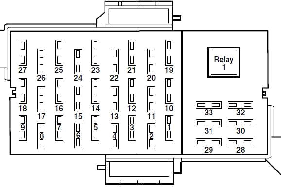
Diagram 2001-2002
| № | A | Protected components |
|---|---|---|
| 1 | — | - |
| 2 | — | - |
| 3 | — | - |
| 4 | 10 | Air Bags |
| 5 | — | - |
| 6 | 15 | Instrument Cluster, Warning Lamps Module, Transmission Control Switch, Lighting Control Module (LCM) |
| 7 | — | - |
| 8 | 25 | Power Train Control Module (PCM) Power Relay, Coil-on -Plugs, Radio Noise Capacitator, Passive Anti-theft System (PATS) |
| 9 | — | - |
| 10 | 10 | Rear Window Defrost |
| 11 | — | - |
| 12 | — | - |
| 13 | 5 | Radio |
| 14 | 10 | Traction Control Switch, Anti-lock Brakes (ABS), Instrument Cluster |
| 15 | 15 | Speed Control Servo, Main Light Switch Illumination, Lighting Control Module (LCM), Clock, Police Power Relay |
| 16 | 15 | Reversing lamps, Turn Signals, Shift Lock, DRL Module, EVO Steering, Electronic Day/Night, Mirror |
| 17 | 30 | Wiper Motor, Wiper Control Module |
| 18 | 30 | Heater Blower Motor |
| 19 | 20 | Auxiliary Power Point |
| 20 | — | - |
| 21 | 15 | Multifunction Switch, Lighting Control Module (LCM), PATS Indicator, Parking Lamps, Instrument Panel Light |
| 22 | 15 | Speed Control Servo, Hazard Lights |
| 23 | 15 | Power Windows/Door Locks, PATS, Exterior Rear View Mirrors, EATC Module, Instrument Cluster, Clock, Lighting Control Module (LCM), Interior Lamps |
| 24 | 10 | Left Hand Low Beam |
| 25 | 20 | Power Point, Cigar Lighter, Emergency Flashers |
| 26 | 10 | Right Hand Low Beam |
| 27 | 25 | Lighting Control Module (LCM), Main Light Switch, Cornering Lamps, Fuel Tank Pressure Sensor |
| 28 | 20 | Power Windows |
| 29 | — | - |
| 30 | — | - |
| 31 | — | - |
| 32 | 20 | ABS Values |
Advertisements
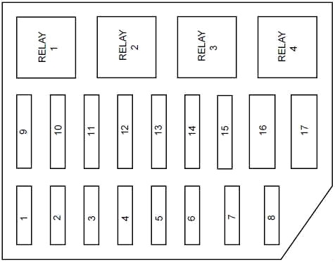
Engine Compartment Fuse Box Diagram
The power distribution box is located in the engine compartment.
| № | A | Protected components |
|---|---|---|
| 1 | 20 | Electric Fuel Pump Relay |
| 2 | 30 | Generator, Starter Relay, Fuses 15 and 18 |
| 3 | 25 | Radio, CD Changer, Subwoofer Amplifier |
| 4 | 30 | Police Power Relay |
| 5 | 15 | Horn Relay |
| 6 | 20 | DRL Module |
| 7 | 20 | Circuit Breaker: Power door Locks, Power Seats, Trunk Lid Release |
| 8 | 30 | Air Suspension System |
| 9 | 50 | See Fuses 5 and 9 |
| 10 | 50 | See Fuses 1, 2, 6, 7, 10, 11, 13 and Circuit Breaker 14 |
| 11 | 40 | 1998-2000: See Fuses 4, 8, 16 and Circuit Breaker 12 |
| 50 | 2001-2002: See Fuses 4, 8, 16 and Circuit Breaker 12 | |
| 12 | 30 | PCM Power Relay, PCM, Natural Gas Vehicle Module |
| 13 | 50 | High Speed Cooling Fan Relay |
| 14 | 40 | Rear Window Defrost Relay, Also see Fuse 17 |
| 15 | 50 | 1998-2000: Anti-Lock Brake Module |
| 40 | 2001-2002: Anti-Lock Brake Module | |
| 16 | 50 | Police Option Fuse Holder |
| 17 | 30 | Cooling Fan Relay |
| R1 | Rear Defrost Relay | |
| R2 | Horn Relay | |
| R3 | Cooling Fan Relay | |
| R4 | Air Suspension Pump Relay, Police Power Relay | |
Additional Relay Box
Located on the left-hand fender affixed to the vacuum reservoir.
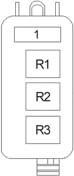
| 1 | PCM Power |
| R1 | A/C WOT Cutout |
| R2 | Fuel Pump |
| R3 | PCM Power |
Advertisements