Advertisements
Fuse box diagram (fuse layout), location and assignment of fuses and relays Ford Contour and Mercury Mystique (1995, 1996, 1997, 1998, 1999, 2000).
Checking and Replacing Fuses
Fuses and circuit breakers protect your vehicle’s electrical system from overloading. If electrical parts in your vehicle are not working, the system may have been overloaded and blown a fuse or tripped a circuit breaker. Before you replace or repair any electrical parts, check the appropriate fuses or circuit breakers.
- Use the charts to decide which fuse you should check.
- On the fuse panel decal located on the cover of the power distribution box or on the end of the instrument panel fuse panel, find the number of the fuse you want to check.
- Find the corresponding fuse and remove it with the fuse pulling tool that is provided.
- Check the fuse to see if it is blown. Look through the clear side of the fuse to see if the metal wire inside is separated. If it is, the fuse should be replaced.
- Replace the fuse with one that has the right amperage rating.
Note
- Before replacing a fuse check that the key has been removed from the ignition and that all the services are switched off and/or disengaged.
- Do not repair fuses and never replace a blown fuse with one that has a higher amp rating. This can cause damage to the electrical system and fire.
- Never replace a broken fuse with anything other than a new fuse. Use always an intact fuse of the same color.
- Do not modify the electrical system of your vehicle in any way. Have repairs to the electrical system and the replacement of relays and high current fuses carried out by properly trained technicians.
- If a fuse blows again contact a qualified service center.
Instrument Panel Fuse Box Diagram
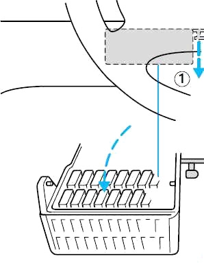
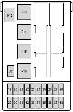
The instrument panel fuse panel is underneath the instrument panel on the left side. To open it, reach under the instrument panel and push the release button to the right of the fuse panel.
| № | A | Fused component |
|---|---|---|
| 19 | 7.5 | 1995-1997: Heated rear view mirrors |
| 20 | 10 | Wiper motors (circuit breaker) |
| 21 | 40 | Power windows |
| 22 | 7.5 | 1995-1997: ABS module |
| 23 | 15 | Backup lamps |
| 24 | 15 | Brake lamps |
| 25 | 20 | Door locks |
| 26 | 7.5 | Main light |
| 27 | 15 | Cigar lighter |
| 28 | 30 | Electric seats |
| 29 | 30 | Rear window defrost |
| 30 | 7.5 | Engine management system |
| 31 | 7.5 | Instrument panel illumination |
| 32 | 7.5 | Radio |
| 33 | 7.5 | Parking lamps - driver's side |
| 34 | 7.5 | Interior lighting/electric mirror adjustment/clock |
| 35 | 7.5 | Parking lamps - passenger’s side |
| 36 | 10 | 1995-1998: Air bag |
| 37 | 30 | Heater blower motor |
| 38 | — | - |
| R12 | Interior lighting | |
| R13 | Rear window defrost | |
| R14 | Heater blower motor | |
| R15 | Wiper motor | |
| R16 | Ignition | |
| D2 | Reverse voltage protection | |
Advertisements
Engine Compartment Fuse Box
To check or replace a fuse or a relay, remove the cover of the fuse box in the engine compartment by releasing the latch and lifting up.
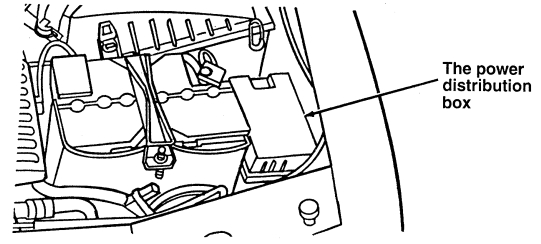
Diagram 1995-1998
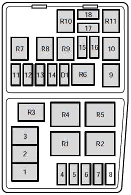
| № | A | Fused component |
|---|---|---|
| 1 | 80 | Main power supply to vehicle electrical system |
| 2 | 60 | Engine cooling fan |
| 3 | 60 | ABS braking system, heater blower |
| 4 | 20 | Ignition, EEC module, Daytime running lights |
| 5 | 15 | Foglamp |
| 6 | — | - |
| 7 | 20 | 1998: ABS system |
| 7 | 30 | 1995-1997: ABS system |
| 8 | 30 | 1995-1998: Air pump |
| 9 | 20 | Electronic Engine Control (EEC) |
| 10 | 20 | Ignition switch |
| 11 | 3 | EEC ignition module (memory) |
| 12 | 15 | Horn and hazard flasher warning system |
| 13 | 20 | 1998: HEGO sensor |
| 13 | 15 | 1995-1998: HEGO sensor |
| 14 | 15 | Electrically operated fuel pump |
| 15 | 10 | Low beam headlamp - (passengers side) |
| 16 | 10 | Low beam headlamp - (driver's side) |
| 17 | 10 | High beam headlamp - (passengers side) |
| 18 | 10 | High beam headlamp - (driver's side) |
| R1 | Daytime running lights | |
| R2 | Radiator fan relay (high speed) | |
| R3 | Air conditioning | |
| R4 | Air conditioning clutch | |
| R5 | Radiator fan relay (low speed) | |
| R6 | Starter solenoid | |
| R7 | Horn | |
| R8 | Fuel pump | |
| R9 | Low beam headlamps | |
| R10 | High beam headlamps | |
| R11 | PCM module | |
| D1 | Reverse voltage protection | |
Advertisements
Diagram 1999-2000
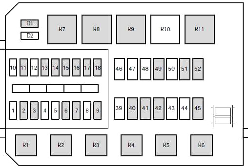
| № | A | Fused component |
|---|---|---|
| 1 | — | - |
| 2 | 7.5 | Alternator |
| 3 | 20 | Foglamps |
| 4 | — | - |
| 5 | — | - |
| 6 | 3 | EEC ignition module (memory) |
| 7 | 20 | Horn and hazard flasher warning system |
| 8 | — | - |
| 9 | 15 | Fuel pump |
| 10 | — | - |
| 11 | 20 | Ignition, Electronic Engine Control |
| 12 | — | - |
| 13 | 20 | HEGO sensor |
| 14 | 7.5 | ABS module |
| 15 | 7.5 | Low beam headlamp (passenger's side) |
| 16 | 7.5 | Low beam headlamp (driver’s side) |
| 17 | 7.5 | High beam headlamp (passenger’s side) |
| 18 | 7.5 | High beam headlamp (driver's side) |
| 39 | — | - |
| 40 | 20 | Ignition, light switch, central junction box |
| 41 | 20 | EEC relay |
| 42 | 40 | Central junction box (fuse 37 to blower relay) |
| 43 | — | - |
| 44 | — | - |
| 45 | 60 | Ignition |
| 46 | — | - |
| 47 | — | - |
| 48 | — | - |
| 49 | 60 | Engine cooling |
| 50 | — | - |
| 51 | 60 | ABS |
| 52 | 60 | Central junction box (central timer module, rear window defrost relay, fuses 24, 25, 27, 28, 34) |
| R1 | Fuel pump | |
| R2 | EEC module | |
| R3 | Air conditioning | |
| R4 | Low beam | |
| R5 | High beam | |
| R6 | Horn | |
| R7 | Starter solenoid | |
| R8 | Engine cooling fan (high speed) | |
| R9 | Engine cooling fan | |
| R10 | - | |
| R11 | Daytime running lights | |
| D1 | Reverse voltage protection | |
| D2 | - | |
Relays Outside the Fuse Boxes
| № | Circuits switched | Location |
|---|---|---|
| R18 | "One touch" switch (drivers window) | Driver’s door |
| R20 | - | — |
| R21 | - | — |
| R22 | Foglamps | Wire shield on instrument panel |
| R23 | Turn signals | Steering column |
| R24 | Panic alarm - driver’s side | Door lock module bracket |
| R25 | Panic alarm - right-hand side | Door lock module bracket |
| R26 | - | — |
| R32 | Hego heater control | Near PCM-Module |
Advertisements
