Advertisements
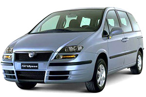
Fuse box diagram (fuse layout), location, and assignment of fuses Fiat Ulysse (2002, 2003, 2004, 2005, 2006, 2007).
Checking and Replacing Fuses
Fuses protect the electrical system: they intervene (blow) in the event of a failure or improper intervention on the system.
When a device does not work, check the condition of its protective fuse: the conductor element A fig. 185 must be intact. If it is not, replace the blown fuse with another with the same amperage (same colour).
Warning!
- Never replace a broken fuse with anything other than a new fuse. Never change a fuse with another amperage: FIRE RISK!
- Do not attempt to repair a blown MAXI-FUSE. Go to a Fiat Dealership.
- Before replacing a fuse, make sure that the ignition key has been removed and that all the other services are switched off and/or disengaged.
- If the fuse blows again, have the vehicle inspected at a Fiat Dealership.
The fuses are contained in three fuseboxes placed respectively:
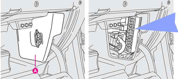
- in the glove compartment; to access it remove the protective cover A;
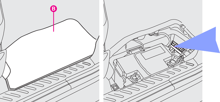
- in the scuttle on the floor in front of the passenger’s seat, next to the battery; to access it remove the protective cover B;
- in the engine compartment; to access it remove the protective cover C.
Glove Compartment Fuse Box Diagram
To access it, remove the protective cover A.
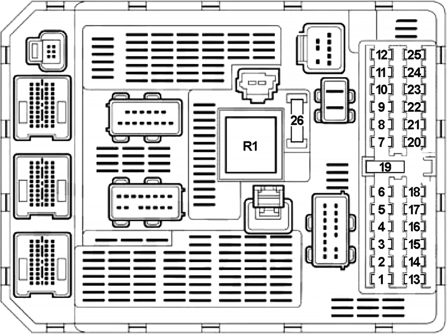
| № | A | Function |
|---|---|---|
| 1 | 10 | Rear Fog Lamp |
| 2 | 15 | Rear Windscreen Wiper |
| 3 | - | - |
| 4 | 15 | Body Computer Node (NBC) Power Supplies |
| 5 | 10 | Left Brake Light |
| 6 | - | - |
| 7 | 20 | Map Reading Courtesy Light, Cigar Lighter, Passenger Side Glove Compartment Light, Automatic Interior Rear View Mirror |
| 8 | - | - |
| 9 | 30 | Front Sun Roof, Front Windscreen Wipers |
| 10 | 15/20 | Diagnostic Socket |
| 11 | 15 | Electronic Alarm, Connect Infotelematic System, Radio, Reconfigurable Multifunction Display, Remote Controls on the Steering Wheel, Particle Filter (JTD versions) |
| 12 | 10 | Right Side Light, Number Plate Lights, Climate Control System Controls Light, Courtesy Lights (First, Second and Third Rows) |
| 13 | - | - |
| 14 | 30 | Central Locking, Superlocking |
| 15 | 30 | Rear Windscreen Washer |
| 16 | 5 | Air Bag System Power Supply, NBC Power Supplies |
| 17 | 15 | Right Brake Light, Third Brake Light, Trailer Brake Lights |
| 18 | 10 | Diagnostic Socket Power Supply, Brake and Clutch Pedal Switches |
| 19 | - | Park Shunt |
| 20 | 10 | Radio Power Supply via NBC |
| 21 | - | - |
| 22 | 10 | Left Side Light, Trailer Side Light |
| 23 | 15 | Electronic Alarm Siren |
| 24 | 15 | Electronic Brake Force Distribution (EBD) Power Supply via NBC |
| 25 | - | - |
| 26 | 40 | Heated Rear Windscreen |
| R1 | Heated Rear Windscreen | |
Advertisements
Battery Compartment Fuse Box Diagram
To access the fuse box remove the protective cover B.
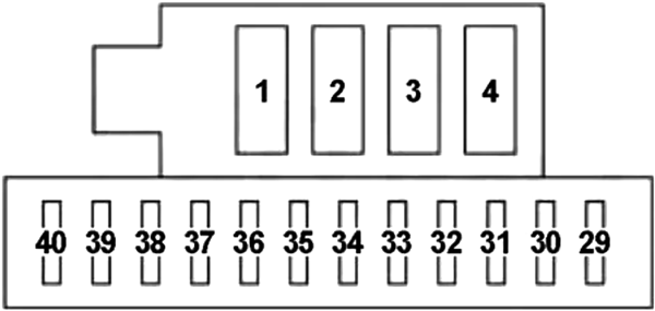
| № | A | Function |
|---|---|---|
| 1 | 40 | Right Electric Sliding Side Door |
| 2 | 40 | Left Electric Sliding Side Door |
| 3 | 30 | HI-FI Amplifier |
| 4 | - | - |
| 29 | - | - |
| 30 | - | - |
| 31 | - | - |
| 32 | 25 | Electrically Adjusted Driver's Seat |
| 33 | 25 | Electrically Adjusted Passenger Seat |
| 34 | 20 | Third Row Sun Roof |
| 35 | 20 | Second Row Sun Roof |
| 36 | 10 | Passenger Heated Seat |
| 37 | 10 | Driver's Heated Seat |
| 38 | 15 | Child Electric Locks |
| 39 | 20 | Third Row 12V Rear Electric Socket |
| 40 | 20 | Driver’s Seat Electric 12V Socket |
Engine Compartment Fuse Box Diagram
To access it remove the protective cover C.
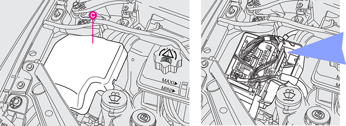
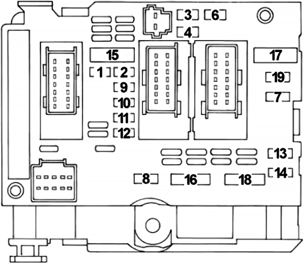
| № | A | Function |
|---|---|---|
| 1 | 10 | Reversing Lights, Gas Discharge Headlamps, Engine Cooling Fan Relay Control, Engine Coolant Level (Diesel), Heater Plugs Node (Diesel), Air Flow Meter (Diesel), Water Presence Sensor (Diesel), Vehicle Speed Sensor (Diesel) |
| 2 | 15 | Fuel Pump, EV EGR (Diesel), EV Turbo Pressure Regulation (Waste Gate Valve) (Diesel) |
| 3 | 10 | ABS/ESP Control Unit |
| 4 | 10 | NCA Control Unit, Starting Relay Control, Shift Lock Relay Control, NCA Shift Lock, Engine Management Control Unit |
| 5 | 10 | Diesel: Additive Injector, NAD |
| 6 | 15 | Fog Light |
| 7 | 20 | Headlamp Washer Pump |
| 8 | 20 | Power Supply for Main Electronic Control Unit, Electric Fan Relay Controls, Turbo Pressure Regulation Solenoid Valve (Waste Gate Valve) (Diesel) |
| 9 | 15 | Left Dipped Headlamp, Front Headlamp Alignment Adjustment Sensor, Rear Lamps Alignment Adjustment Sensor |
| 10 | 15 | Right Dipped Headlamp |
| 11 | 10 | Left Main Beam Headlamp |
| 12 | 10 | Right Main Beam Headlamp |
| 13 | 15 | Horn |
| 14 | 10 | Front Windscreen Washer Pump |
| 15 | 30 | Petrol: Injectors, Ignition Coil, Throttle Valve Node Heater, Canister Filer Scavenging Solenoid Valve, Downstream Lambda Sensor Heating, Upstream Lambda Sensor Heating |
| 30 | Diesel: Diesel Heater, Diesel Injection Pump Solenoid Valve, EGR Throttle Valve Solenoid, Swirl Solenoid Valve, Air Heater Solenoid Valve (2.2 JTD), EGR Solenoid Valve (2.0 JTD) | |
| 16 | 30 | Air Pump |
| 17 | 30 | Front Windscreen Wiper |
| 18 | 40 | Additional Vents (Climate Control System) |
| 19 | - | - |
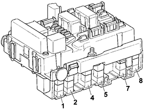
| № | A | Function |
|---|---|---|
| 1 | 50 | Second Speed Fan |
| 2 | 60 | Petrol: ABS |
| 50 | Petrol: ESP | |
| 60 | Diesel: ABR | |
| 3 | 30 | Petrol: ESP Solenoid Valve |
| 30 | Diesel: Burner | |
| 4 | 60 | NBC1 |
| 5 | 70 | NBC2 |
| 6 | 30 | First Speed Fan |
| 7 | 40 | Anti-Theft Device |
| 8 | 50 | Climate Control |
Advertisements
