
Advertisements
Fuse box diagram (fuse layout), location and assignment of fuses and relays Fiat Marea (Type 185) (1997, 1998, 1999, 2000, 2001, 2002).
Checking and Replacing Fuses
A fuse is an element for protecting the electrical system. A fuse will trip (i.e. it will blow) in the event of a failure or improper interventions in the electrical system.
If an electrical device is not working, check whether the respective fuse is blown. The conductor should be intact. If it is not, replace the fuse with another with the same amperage (same color).
Warning!
- Never replace a broken fuse with anything other than a new fuse. Always use a fuse of the same colour.
- Never change a fuse with another amperage: FIRE RISK!
- Do not attempt to repair a blown MAXI-FUSE. Go to a Fiat Dealership.
- Before changing a fuse, check the ignition key has been removed and that all the other electric devices have been turned off/disabled.
- If the fuse blows again, have the vehicle inspected at a Fiat Dealership.
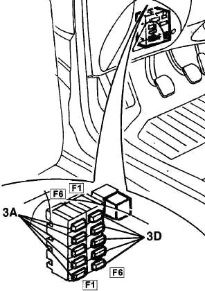
Location of Relays and Fuses in the Passenger Compartment
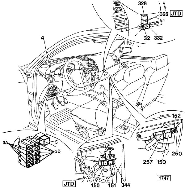
3A/D – Supplementary fuse box
4 – Junction unit
5 – Dipped headlamps relay feed
32 – Fog lamp control relay
150 – Injection system control relay (1747) (JTD)
151 – Lambda probe control relay for fuel pump and injectors
152 – Fuse protecting injection system (1747) (JTD)
250 – Fuse protecting fuel pump (1747)
257 – Fuel pump control relay (1747)
326 – Additional heater control unit
328 – Hazard warning lights relay
332 – Ignition activated power relay
344 – Protection fuse ie. (JTD)
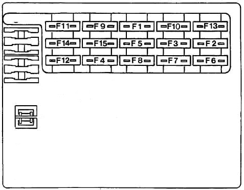
The Instrument Panel Fuse Panel №1
| No | A | Fused component |
|---|---|---|
| 1 | 10 | Brake lights - Additional brake light - Direction indicators - Instrument supply |
| 2 | 10 | Right front side light - Left rear side light - Right number plate light - Radio light - Instrument pane light dimmer - Side lights warning light - Cigar lighter light - Switch panel light - Automatic transmission controls light - Radio phone light - Heater/air conditioning controls light |
| 3 | 10 | Left front side light - Right rear side light - Left number plate light - Mirror controls light |
| 4 | 10 | Right dipped beam headlamp |
| 5 | 10 | Left dipped headlamp - Headlamp alignment corrector - Headlamp washer enablement |
| 6 | 10 | Right main beam headlamp |
| 7 | 10 | Left main beam headlamp - Main beam headlamps warning light |
| 8 | 20 | Central locking - Luggage compartment light |
| 9 | 10 | Hazard warning lights |
| 10 | 10 | Interior lights (front and rear) - Instrument supply - Remote control receive and alarm control unit supply - Radio phone supply |
| 11 | 30 | Heated rear windscreen - Mirror demisting |
| 12 | 30 | Car interior climate control fan motor (air conditioning) |
| Air conditioning control unit | ||
| 13 | 20 | Horns |
| 14 | 20 | Windscreen wiper - Rearscreen wiper - Windscreen/rearscreen washer - Headlamp washer enablement |
| 15 | 20 | Air conditioning control unit - Vehicle interior fan motor (with heater) |
Advertisements
The Instrument Panel Fuse Panel №2
| № | A | Fused component |
|---|---|---|
| 1 | 7.5 | Injection memory and CODE |
| 2 | 7.5 | Compressor and air conditioner |
| 3 | 10 | ABS |
| 4 | 7.5 | Injection and CODE |
| 5 | 20 | Headlamp washers |
| 6 | 7.5 | Ignition activated services (15/54) |
| 1 | 7.5 | Ignition activated services (INT) |
| 2 | 15 | Foglamps |
| 3 | 25 | Rear electric windows |
| 4 | 25 | Front electric windows |
| 5 | 30 | Sun roof, seats, cigar lighter |
| 6 | 10 | Airbag |
Location of Relays and Fuses in the Engine Compartment
Petrol Engine
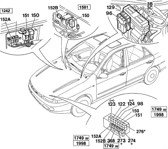
(*) 1581 with automatic transmission. (**) Versions with air conditioning.
3B-3C – Power fuse box
96 – Power fuse-protecting ABS
98 – Headlamp washer intermittent function
122 – Engine cooling fan low-speed relay
123 – Engine cooling fan high-speed timer
124 – Air conditioning compressor control relay
129 – Power fuse protecting engine cooling fan
150 – Injection system relay feed
151 – Lambda probe control relay for fuel pump and injectors
152 – Fuse protecting injection system
152A – Fuse protecting injection system
152B – Fuse protecting injection system
273 – Fuse protecting automatic transmission system
274 – Fuse protecting automatic transmission system
276 – Starter enablement relay
368 – Relay diode for injection system control
Diesel Engine
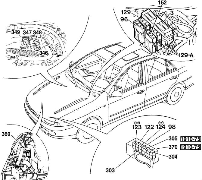
(**) Versions with air conditioning.
3A/D – Supplementary fuse box
4 – Junction unit
5 – Dipped headlamps relay feed 32 Fog lamp control relay
150 – Injection system control relay (1747) (JTD)
151 – Lambda probe control relay for fuel pump and injectors
152 – Fuse protecting injection system (1747) (JTD)
250 – Fuse protecting fuel pump (1747)
257 – Fuel pump control relay (1747)
326 – Additional heater control unit
328 – Hazard warning lights relay
332 – Ignition activated power relay.
344 – Protection fuse ie. (JTD)
Advertisements
Engine Compartment Fuse Box Diagram
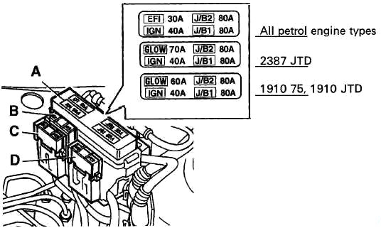
| № | A | Fused component |
|---|---|---|
| EFI | 30 | Petrol engine: Electronic injection |
| GLOW | 60 | 1910 75, 1910 JTD: Plug |
| 70 | 2387 JTD: Plug | |
| IGN | 40 | Ignition switch |
| J/B1 | 80 | Master supply |
| J/B2 | 60 | Petrol engine: Master supply |
| 80 | Diesel engine: Master supply | |
| B | 30 | Petrol engine without air conditioner: Fan |
| 40 | Engine 1242, 1581, 1747 updated. 99 with air conditioner, JTD, 1910 TD 75: Fan | |
| 50 | Engine 1747, 1998 with air conditioner: Fan | |
| C | 60 | ABS |
| D | 40 | Second fan (TD) |
| E | 30 | Electronic injection (JTD) |
Advertisements