
Advertisements
Fuse box diagram (fuse layout), location, and assignment of fuses and relays Fiat Bravo (2007, 2008, 2009, 2010, 2011, 2012, 2013, 2014).
Checking and Replacing Fuses
Fuses protect the electrical system: they intervene (blow) in the event of a failure or improper intervention on the system.
When a device does not work, check the condition of its protective fuse: the conductor element A fig. 185 must be intact. If it is not, replace the blown fuse with another with the same amperage (same colour).
Warning!
- Never replace a broken fuse with anything other than a new fuse. Never change a fuse with another amperage: FIRE RISK!
- Do not attempt to repair a blown MAXI-FUSE. Go to a Fiat Dealership.
- Before replacing a fuse, make sure that the ignition key has been removed and that all the other services are switched off and/or disengaged.
- If the fuse blows again, have the vehicle inspected at a Fiat Dealership.
The fuses are grouped in three fuse boxes:
- dashboard fuse box;
- luggage compartment fuse box;
- engine compartment fuse box.
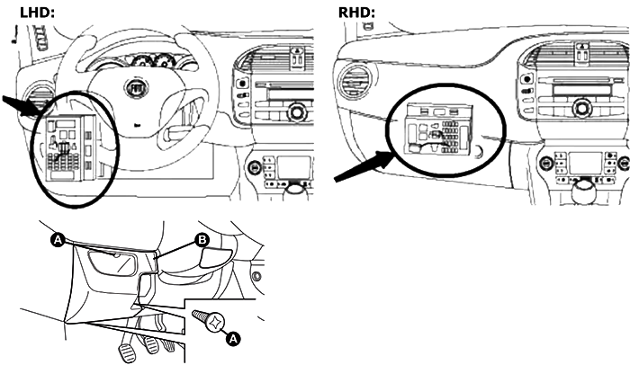
Dashboard Fuse Box Diagram
To access the dashboard fuse box (left-hand drive), loosen the three screws A and remove the flap B.
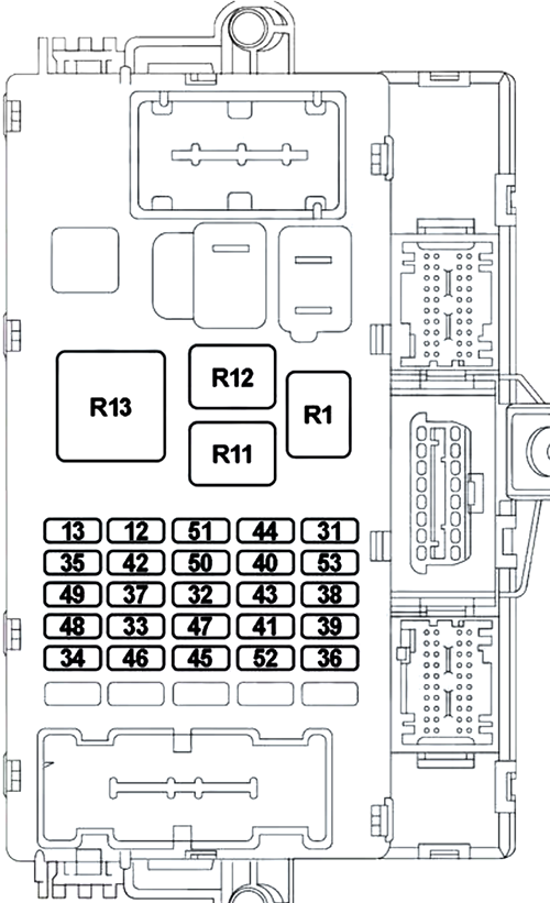
| № | A | Function |
|---|---|---|
| 12 | 7.5 | Right Dipped Headlamp |
| 15 | Xenon: Right Dipped Headlamp | |
| 13 | 7.5 | Left Dipped Headlamp, Headlamp Alignment Corrector |
| 15 | Xenon: Left Dipped Headlamp, Headlamp Alignment Corrector | |
| 31 | 5 | Remote Switch Coils on Fuse Box in Engine Compartment (CVM), Body Computer Control Unit (NBC) |
| 32 | 15 | Hi-Fi Audio Subwoofer Amplifier, Radio and Radio Navigator Sound System (1.4 Turbo MultiAir versions with optional Hi-Fi) |
| 33 | 20 | Left Rear Electric Window |
| 34 | 20 | Right Rear Electric Window |
| 35 | 5 | Reversing Lights, Brake Pedal Control (NC Contact), Presence of Water in Diesel Sensor, Flow Meter, Control On Clutch Pedal qnd Servo Brake Pressure Sensor (1.4 Turbo MultiAir versions) |
| 36 | 20 | Door Locking Control Unit (CGP) (Door Opening/Closing, Safe Lock, Tailgate Release) |
| 37 | 7.5 | Brake Pedal Control (Normally Closed Contact NA), Third Brake Light, Instrument Panel, Xenon Bulbs Control Units |
| 38 | - | - |
| 39 | 10 | Radio and Radio Navigator (excluding 1.4 Turbo MultiAir versions with Optional Hi-Fi), Radio Wiring, Connect Nav +, Bluetooth, Alarm Siren (CSA), Alarm Sensors, Climate Control/Internal Cooling Unit System, Tyre Pressure Monitoring Control Unit (CPP), Diagnostic Connector, Rear Courtesy Lights, Diagnostic Socket Connector |
| 40 | 30 | Heated Rear Window |
| 41 | 7.5 | Electric Door Mirror Defrosters, Defrosters on Front Nozzles |
| 42 | 5 | Braking System Control Unit (NFR), Yaw Sensor (YRS) |
| 43 | 30 | Windscreen Wiper, Bi-Directional Windscreen, Window Washer Electric Pump System on Steering Column Stalk |
| 44 | 15 | Power Socket, Cigar Lighter on Tunnel |
| 45 | - | - |
| 46 | 20 | Sun Roof Motor |
| 47 | 20 | Front Left Electric Window |
| 48 | 20 | Front Right Electric Window |
| 49 | 5 | Emergency Control Panel (Lighting), Centre Control Panel, Controls on Steering Wheel (Lighting), Controls on Front Courtesy Light (Lighting), Volumetric Protection Alarm System Control Unit (Deactivation), Electric Sun Roof System, Rain/Dusk Sensor, Front Seat Heater Pad Controls |
| 50 | 7.5 | Air Bag Control Unit |
| 51 | 5 | Internal Cooling Unit System, Sound System Presetting, Connect Nav +, Bluetooth System Control Unit, Cruise Control Lever, Parking Sensor Control Unit (NSP), Air Quality Sensor (AQS), Automatic Air-Conditioner, Electric Door Mirrors (Moving, Folding), Tyre Pressure Monitoring Control Unit (CPP), Voltage Stabiliser (1.4 Turbo MultiAir versions) |
| 52 | 15 | Rear Window Wiper |
| 53 | 7.5 | Instrument Panel, Rear Fog Light |
| R1 | Dipped Headlamp, Headlamp Alignment Corrector | |
| R11 | Heated Rear Windscreen, Mirror Defrosting | |
| R12 | Ignition Discharge NT/A (Windscreen/Rearscreen Washwipe System, Power Socket) | |
| R13 | Power Supply + Battery for Electric Windows, Electric Sun Roof Systems | |
Advertisements
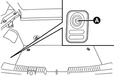
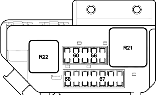
Luggage Compartment Fuse Box Diagram
To access the fuse box located on the left side of the luggage compartment, open lid A.
Type 1
| № | A | Function |
|---|---|---|
| 56 | 30 | Front Left Seat Movement Control Unit |
| 60 | 30 | Front Left Seat Movement Control Unit |
| 67 | 10 | Front Left Seat Heating Pad |
| 68 | 10 | Front Left Seat Heating Pad |
| R21 | Front Left Seat Heating Pad | |
| R22 | Front Right Seat Heating Pad | |
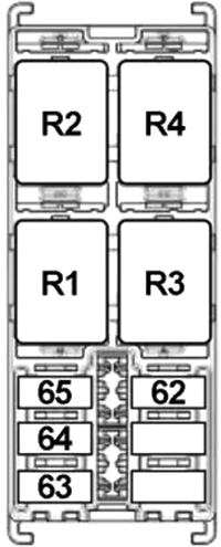
Type 2
| № | A | Function |
|---|---|---|
| 62 | 10 | Right Front Seat Heating |
| 63 | 30 | Front Right Seat Movement |
| 64 | 30 | Front Left Seat Movement |
| 65 | 10 | Left Front Seat Heating |
| R1 | - | |
| R2 | - | |
| R3 | Left Front Seat Heating | |
| R4 | Right Front Seat Heating | |
Advertisements
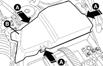
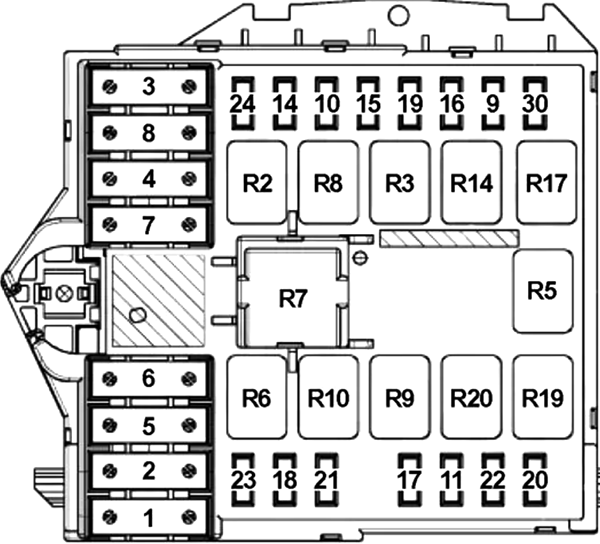
Engine Compartment Fuse Box Diagram
To access the fuse box next to the battery, press retaining clips A and remove protection cover B.
Type 1
| № | A | Description |
|---|---|---|
| 1 | 40 | Braking System Control Unit |
| 2 | 50 | Dashboard Control Unit |
| 3 | 30 | Ignition Switch |
| 4 | 30 | Selespeed Gearbox Control Unit, Headlamp Washer Electric Pump |
| 5 | 50 | Diesel: Glow Plug Preheating Control Unit |
| 6 | 20 | Engine Cooling Fan (Low Speed/One Speed) |
| 30 | Engine Cooling Fan (Low Speed/One Speed) | |
| 40 | Engine Cooling Fan (Low Speed/One Speed) | |
| 7 | 40 | Engine Cooling Fan (High Speed) |
| 50 | Engine Cooling Fan (High Speed) | |
| 8 | 30 | Climate Control Fan |
| 40 | Climate Control Fan | |
| 9 | 7.5 | Fog Light, Right Cornering Light |
| 30 | Headlight Washer Pump | |
| 10 | 10 | Horn |
| 11 | 15 | Engine Management System Secondary Loads (Lambda Sensor, Canister Solenoid Valve, PDA System Solenoid Valve, EGR Solenoid Valve, Throttle Solenoid Valve, VGT Solenoid Valve, Glow Plug Warming Control Unit) |
| 14 | 7.5 | Right Main Beam Headlamp |
| 15 | Main Beam Headlights | |
| 15 | 7.5 | Left Main Beam Headlamp |
| 30 | Additional Heater (PTC1) | |
| 16 | 7.5 | Engine Management Control Unit, Gearbox Control Unit |
| 17 | 10 | Engine Management Control Unit |
| 18 | 10 | Engine Management Control Unit, Gearbox Control Unit |
| 19 | 7.5 | Air Conditioning Compressor |
| 20 | 20 | Headlamp Washer Electric Pump |
| 21 | 15 | Fuel Pump in Tank |
| 22 | 15 | Petrol: Engine Management System Primary Loads (Injectors, Ignition Coils) |
| 20 | Diesel: Engine Management System Primary Loads (Injectors, Ignition Coils, Engine Control Unit) | |
| 23 | 30 | Braking System Control Unit (NFR) (Electronic Control Unit, Solenoid Valves) |
| 24 | 7.5 | Electric Steering Control Unit (NGE) |
| 30 | 7.5 | Fog Light, Left Cornering Light |
| 15 | Left Right Fog Light, Cornering Light | |
| R2 | Main Beam Headlamp | |
| R3 | Horn | |
| R5 | Air Conditioning Compressor | |
| R6 | Engine Cooling Fan (Low Speed/One Speed) | |
| R7 | Engine Cooling Fan (High Speed) | |
| R8 | Passenger Compartment Cooling Fan | |
| R9 | Engine Management System | |
| R10 | Fuel Pump | |
| R14 | Fog Light, Left Cornering Light | |
| R17 | Fog Light, Right Cornering Light | |
| R19 | Headlamp Washer Electric Pump | |
| R20 | Selespeed Gearbox Control Unit | |
| 1.4 16v: Headlamp Washer Electric Pump | ||
Type 2
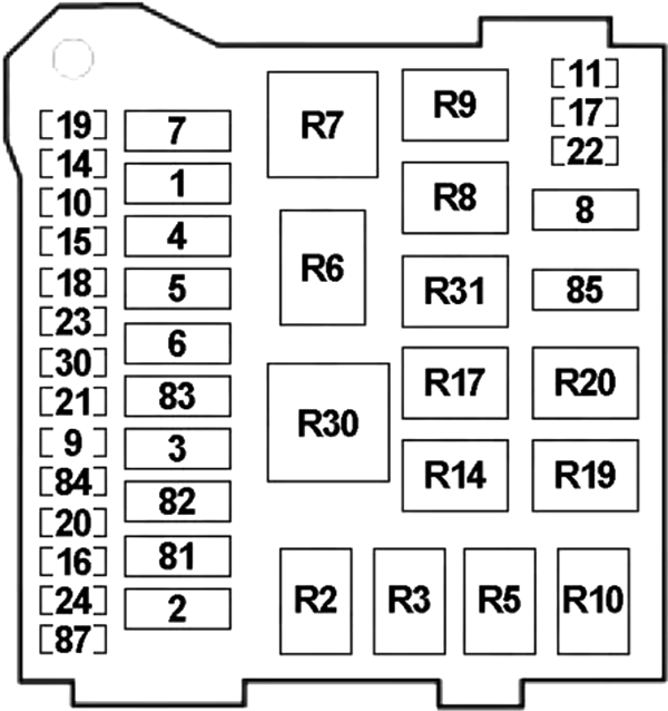
| № | A | Description |
|---|---|---|
| 1 | 70 | NBC/CPL |
| 2 | 50 | CPL |
| 3 | 20 | Ignition Switch |
| 4 | 40 | Braking System Control Unit (NFR) (Pump) |
| 5 | 70 | Electric Steering Control Unit (NGE) |
| 6 | 20 | Engine Cooling Electric Fan Low Speed |
| 30 | Engine Cooling Electric Fan Low Speed | |
| 40 | Engine Cooling Electric Fan Low Speed | |
| 7 | 40 | Engine Cooling Electric Fan High Speed |
| 50 | Engine Cooling Electric Fan High Speed | |
| 8 | 40 | Climate Control System Fan |
| 9 | 30 | Headlight Washer Pump |
| 10 | 10 | Horns |
| 11 | 10 | Engine Control Unit (NCM) (Secondary Loads) |
| 15 | Engine Control Unit (NCM) (Secondary Loads) | |
| 14 | 15 | Main Beam Headlights |
| 15 | 30 | Heater PTC 1 |
| 16 | 5 | +15/54 Engine Control Unit (NCM) |
| 17 | 10 | Engine Control Unit (NCM) (Main Loads) |
| 15 | Engine Control Unit (NCM) (Main Loads) | |
| 18 | 5 | Engine Control Unit (NCM) |
| 19 | 7.5 | Air Conditioning Compressor |
| 20 | 30 | NCR (Pump) |
| 15 | LPG Injectors | |
| 22 | 15 | Electrical System Primary Loads |
| 20 | Electrical System Primary Loads | |
| 23 | 30 | Braking System Control Unit (NFR) (Valves) |
| 24 | 5 | NGE |
| 30 | 15 | Fog Lights |
| 81 | 60 | Glow Plug Preheating Control Unit (JTD) |
| 82 | 50 | Heater PTC2 |
| 84 | 10 | Robotised Gearbox (Control Unit) |
| 7.5 | LPG Solenoid Valve | |
| 85 | 15 | Fuel Pump |
| 87 | 5 | Robotised Gearbox (Gearbox Controls) |
| 5 | Voltage Stabiliser (Start & Stop) | |
| R2 | Main Beam Headlamp | |
| R3 | Horn | |
| R5 | Air Conditioning Compressor | |
| R6 | Engine Cooling Fan (Low Speed/One Speed) | |
| R7 | Engine Cooling Fan (High Speed) | |
| R8 | Climate Control System Fan | |
| R9 | Engine Management System | |
| R10 | Start-Up Inhibition (Start & Stop) | |
| LPG Injectors | ||
| R14 | Left Fog Light | |
| R17 | Headlight Washers | |
| R19 | Right Fog Light | |
| R20 | LPG Solenoid Valves | |
| Starting Inhibition (with Robotised Gearbox) | ||
| Start-Up Enablement (Start & Stop) | ||
| R31 | Fuel Pump | |
Control Box on Battery Positive Pole (CBA)
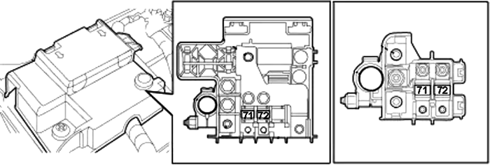
| № | A | Description |
|---|---|---|
| 71 | 70 | Dashboard Control Unit (CPL) |
| 72 | 70 | Electric Steering Control Unit (NGE) |
| 73 | - | - |
Advertisements