Advertisements
Fuse box diagram (fuse layout) and assignment of fuses and relays Dodge Sprinter (2003, 2004, 2005, 2006).
Checking and Replacing Fuses
Fuses protect the car’s electrical systems from short circuits. To check a fuse, look at the silver-colored band inside the fuse. If the band is broken or melted, replace the fuse. Be sure to replace a bad fuse with a new one of the identical size and rating.
Fuses of the same amperage can be temporarily borrowed from another fuse location if a fuse goes out. Replace the fuse as soon as possible.
Note
- Before replacing a fuse check that the key has been removed from the ignition and that all the services are switched off and/or disengaged.
- When replacing a blown fuse, it is important to use only a fuse having the correct amperage rating. The use of a fuse with a rating other than indicated may result in a dangerous electrical system overload.
- If a properly rated fuse continues to blow, it indicates a problem in the circuit that must be corrected.
Fuse Box №1
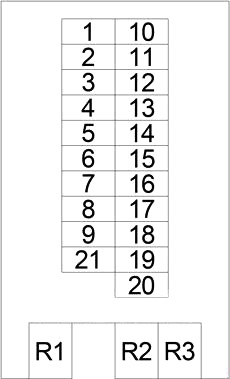
| № | A | Circuit Protected |
|---|---|---|
| 1 | 10 | Headlamp Switch |
| 2 | 10 | Headlamp Right (High Beam) |
| 3 | 10 | Headlamp Left (High Beam), Instrument Cluster |
| 4 | 10 | Shifter Assembly |
| 5 | 10 | Stop Lamp Switch, Data Link Connector |
| 6 | 20 | Multi-Function Switch (Wiper/Turn Signal/Engine Start Control Module) |
| 7 | 15 | Optional Equipment Relay, Lamp Relay - Right (Trailer Tow Connector, Tail Lamp, Headlamp), Sentry Key Remote Entry Module, Horn (VTSS), Rear Window Defogger Switch, Circulation Pump Relay, Transmission Control Relay, Horn Relay |
| 8 | 20 | Cigar Lighter, Radio, Auxiliary Heater Switch, Turn Signal/Anti-Theft Alarm Relay - Left/Right, Courtesy Lamp, Interior Lamp, Dome Lamp |
| 9 | 15 | Multi-Function Switch (Hazard Warning Switch) |
| 10 | 10 | Map/Reading Lamp Switch, Interior Light Switch, Radio, A/C Fan Switch, Automatic Temperature Control Module, Headlamp Adjust Switch, Panic Alarm Switch, A/C Switch - Roof, Temperature Switch, Shifter Assembly, TCS Switch (ASR), Master Door Lock Switch, Towing/Intrusion Sensor On/Off Switch, Ash Receiver Lamp, Fog Lamp Switch, Rear Window Defogger Switch, Locker Switch №1, Cigar Lighter Lamp |
| 11 | 10 | Left Lamp Relay (Headlamp, Tail Lamp) |
| 12 | 10 | Headlamp Right (Low Beam), Daytime Running Lamp Relay - Right |
| 13 | 10 | Headlamp Left (Low Beam), Daytime Running Lamp Relay - Left |
| 14 | 15 | Fog Lamp Relay |
| 15 | 10 | Radio, Radio/Cellular Antenna, Central Timer Module, |
| 16 | 15 | Engine Control Module |
| 17 | 15 | Engine Control Module, EGR Valve, Crankcase Heater |
| 18 | 15 | Run-Start Relay, Engine Control Module, Instrument Cluster, Airbag Control Module |
| 19 | 15 | - |
| 20 | 15 | Circulation Pump Relay, Automatic Temperature Control Module |
| 21 | 30 | Blower Motor |
| R1 | Engine Control | |
| R2 | Wiper On/Off | |
| R3 | Turn Signal | |
Advertisements
Fuse Box №2

| № | A | Circuit Protected |
|---|---|---|
| 1 | 10 | Daytime Running Lamp Relay (Instrument Cluster, Headlamp Left, Headlamp Right, License Plate Lamp, Marker Lamp) |
| 2 | 10 | Transmission Control Relay |
| 3 | 15 | Instrument Panel Socket |
| 4 | 7.5 | Left Lamp Relay, Right Lamp Relay |
| 5 | 25 | Central Timer Module |
| 6 | 7.5 | Data Link Connector, Instrument Cluster |
| 7 | 25 | Power Window Switch - Driver |
| 8 | 10 | Power Mirror Switch, Driver/Passenger Power Mirror Motor |
| 9 | 15 | A/C Switch - Roof, Rear Window Defogger Module, Central Timer Module, D+ Relay №2, Daytime Running Lamp Relay, Right Lamp Relay, Auxiliary Battery Relay |
| 10 | 7.5 | Daytime Running Lamp Relay (Right Side) |
| 11 | 7.5 | Daytime Running Lamp Relay (Left Side) |
| 12 | 25 | Body Plug Connector |
| 13 | 15 | Run-Start Relay |
| 14 | 10 | D+ Relay 2 |
| 15 | 25 | Power Window Switch - Master, Power Window Switch - Passenger |
| 16 | - | |
| 17 | - | |
| 18 | - |
Fuse Box №3
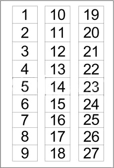
| № | A | Circuit Protected |
|---|---|---|
| 1 | 7.5 | Auxiliary Heater Timer |
| 2 | 7.5 | Security System Module, Siren, Intrusion Sensor №1/№2/№3 |
| 3 | 25 | Auxiliary Heater Relay |
| 4 | 25 | Cabin Heater Assembly |
| 5 | 7.5 | Fog Lamp Switch |
| 6 | 25 | Trailer Tow Control Module, Trailer Tow Connector |
| 7 | 10 | Circulation Pump Diode, Cabin Heater Assembly, Auxiliary Heater Relay |
| 8 | 10 | Fan Stage 1 Relay |
| 9 | 30 | CTEL Connector |
| 10 | 15 | Security System Module |
| 11 | 25 | Warm Air Auxiliary Heater Assembly |
| 12 | 15 | Locker Switch №1/№2 |
| 13 | 7.5 | CTEL Connector |
| 14 | 7.5 | Security System Module |
| 15 | 15 | Driver/Passenger Heated Seat Switch |
| 16 | - | |
| 17 | - | |
| 18 | 15 | Map/Reading Lamp Switch, Interior Light Switch, Time Delay Relay, |
| 19 | 15 | |
| 20 | 15 | A/C Fan Switch |
| 21 | - | |
| 22 | - | |
| 23 | - | |
| 24 | - | |
| 25 | - | |
| 26 | - | |
| 27 | - |
Advertisements
Fuse Box №4
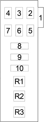
| № | A | Circuit Protected |
|---|---|---|
| 1 | 30 | A/C Auxiliary Fan Relay |
| 2 | - | - |
| 3 | - | - |
| 4 | - | - |
| 5 | 10 | Sentry Key Remote Entry Module, Turn Signal/Anti-Theft Alarm Relay - Left, Turn Signal/Anti-Theft Alarm Relay - Right |
| 6 | 7.5 | ABS |
| 7 | 25 | ABS |
| 8 | 40 | A/C Control Module - Roof |
| 9 | 40 | ABS |
| 10 | 30 | Rear Window Defogger Module, Rear Window Defogger Relay - Left, Rear Window Defogger Relay - Right |
| R1 | - | |
| R2 | Starter | |
| R3 | - | |
Relay Box
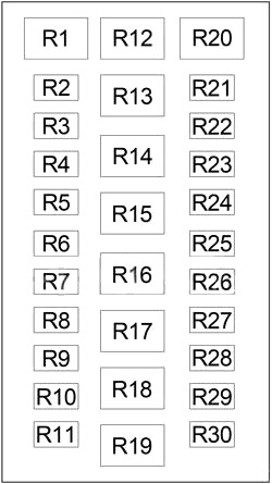
| № | Relay |
|---|---|
| R1 | - |
| R2 | Turn Signal/Anti-Theft Alarm - Left |
| R3 | Turn Signal/Anti-Theft Alarm - Right |
| R4 | Lamp - Left |
| R5 | Lamp - Right |
| R6 | Transmission Control |
| R7 | D+ №1 |
| R8 | Daytime Running Light |
| R9 | Fog Lamp |
| R10 | Daytime Running Lamp - Left |
| R11 | Daytime Running Lamp - Right |
| R12 | Circulation Pump |
| R13 | Run-Start |
| R14 | Time Delay |
| R15 | Auxiliary Heater |
| R16 | Optional Equipment |
| R17 | Fan Stage 1 |
| R18 | A/C Auxiliary Fan |
| R19 | - |
| R20 | - |
| R21 | Auxiliary Battery |
| R22 | D+ №2 |
| R23 | Rear Window Defogger - Left |
| R24 | - |
| R25 | Rear Window Defogger - Right |
| R26 | - |
| R27 | - |
| R28 | - |
| R29 | - |
| R30 | - |
Fusible Link Block
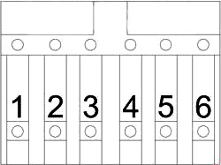
| № | A | Circuit Protected |
|---|---|---|
| 1 | 200 | Generator |
| 2 | 70 | Optional Equipment Relay (Fuse Box No,2: "6", "7", "8", "15"; Fuse Box №3: "7", "12", "13", "14", "15", "20"; Fuse Box №4: "6") |
| 3 | 125 | D+ Relay №1 (Fuse Box No,2: "9", "10", "11"), Fuse Box No,2: "1", "2", "3", "4", "5", "6", "12", "13", "14"; Fuse Box No,3: "1", "3", "4", "5", "6", "8", "9", "11", "18", Fuse Box №4: "1", "5", "6", "7", "8", "9", "10" |
| 4 | 80 | - |
| 5 | 125 | Glow Plug Control Module |
| 6 | 100 | Ignition Switch, Engine Control Relay, Starter Relay, Fuse Box №1: "6", "8", "9", "17", "19", "20", "21"; Fuse Box No,3: "2", "10" |
Advertisements
