Advertisements
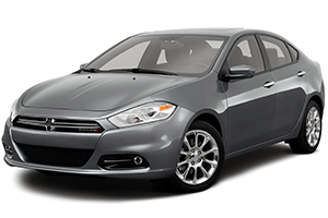
Fuse box diagram (fuse layout), location, and assignment of fuses for Dodge Dart (2013, 2014, 2015, 2016).
Checking and Replacing Fuses
To prevent damage to the electrical system due to short circuiting or overloading, each individual circuit is provided with a fuse. There are fuse blocks in the passenger compartment and in the engine compartment.
Note
- When replacing a blown fuse, always use an appropriate replacement fuse with the same amp rating as the original fuse. Never replace a fuse with another fuse of higher amp rating. Never replace a blown fuse with metal wires or any other material. Failure to use proper fuses may result in serious personal injury, fire and/or property damage.
- Before replacing a fuse, make sure that the ignition is off and that all the other services are switched off and/or disengaged.
- If the replaced fuse blows again, contact an authorized dealer.
- If a general protection fuse for safety systems (air bag system, braking system), power unit systems (engine system, gearbox system) or steering system blows, contact an authorized dealer.
Underhood Fuse Box Diagram
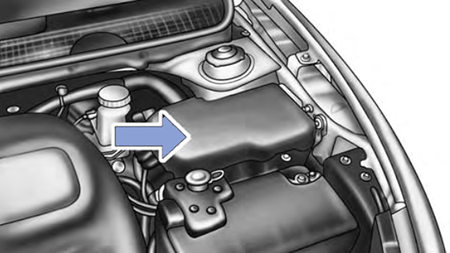
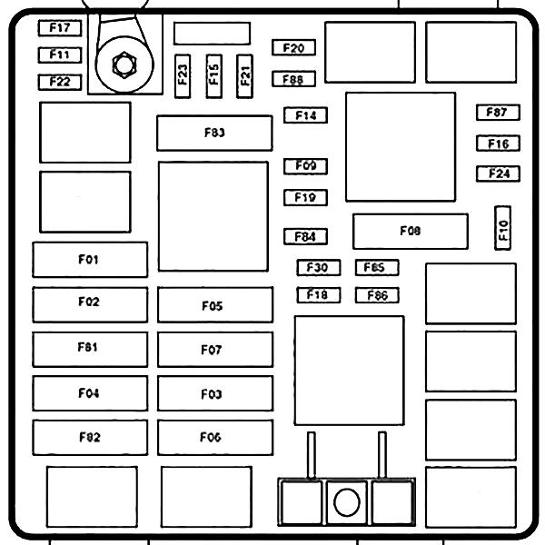
The Power Distribution Center is located on the right side of the engine compartment, behind the battery. This center contains maxi fuses, mini fuses, relays, and circuit breakers. The cavity number of each fuse is stamped on the inside cover.
| № | Maxi Fuse | Mini Fuse | Description |
|---|---|---|---|
| F01 | 70A Tan | - | Body Control Module #1 |
| F02 | 60A Blue | - | Body Control Module #2 |
| F03 | 30A Green | - | Output For Starter Relay #1 |
| F04 | 40A Orange | - | ESC Pump Motor |
| F05 | 40A Orange | - | Transmission Control Module #1 (SDU) |
| F06 | 30A Green | - | Body Control Module #3 |
| F07 | 40A Orange | - | EBL RLY Coil, Blower Motor RLY Coil |
| F09 | - | 5A Tan | Radiator Fan |
| F10 | - | 10A Red | ORC |
| F11 | - | 20A Yellow | 2013: ECM, EPS, Backup Lamp Switch |
| - | 20A Yellow | 2014-2016: Run/Start, Engine Control Module | |
| F14 | - | 15A Blue | Transmission Control Module #2 |
| F15 | - | 15A Blue | Transmission Control Module #3 |
| F16 | - | 15A Blue | 2013: Ignition Coils, Coil Capacitor |
| - | 15A Blue | 2014-2016: Engine Control Module, Ignition Coils | |
| F17 | - | 15A Blue | 2013: ESC, Brake Pedal Switch, OCM |
| - | 15A Blue | 2014-2016: Brake System Module | |
| F18 | - | 20A Yellow | Engine Control Module |
| F19 | - | 10A Red | A/C Compressor Clutch |
| F20 | - | 30A Green | Rear Defroster (EBL) |
| F21 | - | 20A Yellow | Fuel Pump |
| F22 | - | 10A Red | Occupant Restraint Controller (ORC) |
| F23 | - | 25A Clear | Brake System Module (ESC) |
| F24 | - | 20A Yellow | 2013: ECM, Fuel Injectors, Active Grill Shutter (AGS) |
| - | 20A Yellow | 2014-2016: Engine Control Module, Fuel Injectors | |
| F30 | - | 20A Yellow | Power Outlet (Console) |
| F81 | 60A Blue | - | Interior PDC Battery Feed, Power Seats |
| F82 | 30A Green | - | Amplifier |
| F83 | 40A Orange | - | HVAC Blower Motor |
| F84 | - | 20A Yellow | Cigar Lighter |
| F85 | - | 10A Red | Sunroof, LRSM, Power Outlet (Console), UCI/AUX Port, Cigar Lighter |
| F86 | - | 20A Yellow | - |
| F87 | - | 10A Red | Wastegate, Purge Solenoid, OBD Vent Valve, Oxygen Sensor Heaters |
| F88 | - | 10A Red | Heated Outside Mirrors |
Advertisements
Interior Fuse Box Diagram
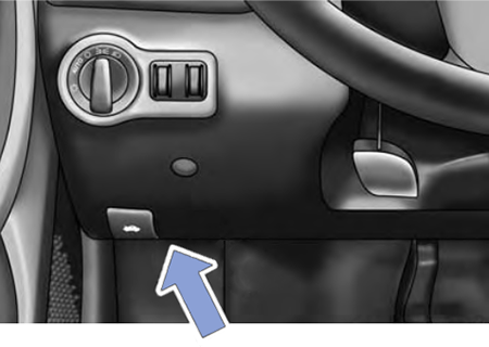
The interior fuses are located on the drivers side under the instrument panel.
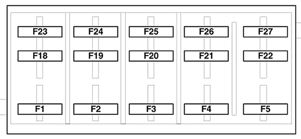
| № | A | Description |
|---|---|---|
| F1 | 20A Yellow | Front Heated Seats - If Equipped |
| F2 | 20A Yellow | Rear Heated Seats, Heated Steering Wheel - If Equipped |
| F3 | 10A Red | Park Assist Module, Rear Camera, Left and Right Blind Spot Sensor, Compass - If Equipped |
| F4 | 15A Blue | Instrument Cluster |
| F5 | 10A Red | HVAC, Humidity Sensor, In-Vehicle Temperature Sensor, Inside Mirror Assembly |
| F19 | 10A Red | 2013-2014: Fuel Door |
| 10A Red | 2015-2016: - | |
| F18 | 15A Blue | Radio |
| F20 | 10A Red | Steering Column Control Module, Switch Bank |
| F21 | 10A Red | Diagnostic Port |
| F22 | 10A Red | Universal Garage Door Opener, EOM |
| F23 | 20A Yellow | Sunroof |
| F24 | 5A Tan | 2013: Direct Battery For Underhood PDC (RLY Coils) |
| 5A Tan | 2014-2016: Rim/Accessory Relay | |
| F25 | 5A Tan | Transmission Control Module #4 |
| F26 | 5A Tan | Stop Lamp Switch |
| F27 | 10A Red | Pneumatic Lumbar Support |
Body Control Module (BCM)
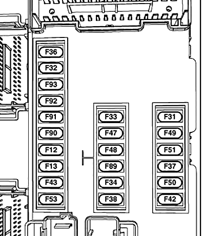
| № | A | Description |
|---|---|---|
| F12 | - | Spare |
| F13 | 15A Blue | Left Headlamp |
| F31 | - | Spare |
| F32 | 10A Red | Interior Lighting / Decklid / Liftgate Release |
| F33 | 25A Clear | Window Motor - Driver |
| F34 | 25A Clear | Window Motor - Passenger |
| F36 | 15A Blue | Intrusion Module |
| F37 | 10A Red | Instrument Panel Cluster |
| F38 | 20A Yellow | Door Locks |
| F42 | - | Spare |
| F43 | 20A Yellow | Windshield Washer Pump |
| F47 | 5A Tan | Transmission Control Module (Tcm) |
| F48 | 20A Yellow | Spare |
| F49 | 7.5A Brown | Stop Lamp Switch |
| F50 | 7.5A Brown | Pneumatic Lumbar Support |
| F51 | 7.5A Brown | Cd / Hands-Free Module - Bluetooth / Radio Display |
| F53 | 7.5A Brown | Driver Window Switch / Power Mirrors |
| F89 | 5A Tan | Trunk Lamp |
| F90 | 7.5A Brown | Front Fog Lamps - Right |
| F91 | 7.5A Brown | Front Fog Lamps - Left |
| F92 | 7.5A Brown | High Beams (Shutters) |
| F93 | 15A Blue | Right Headlamp |
Advertisements
