
Advertisements
Fuse box diagram (fuse layout), location and assignment of fuses Citroen Relay (2006, 2007, 2008, 2009, 2010, 2011, 2012, 2013, 2014).
Checking and Replacing Fuses
The wiring circuits in the vehicle are protected from short circuits by fuses. This greatly reduces the chance of damage caused by electrical problems.
To check a fuse, look at the silver-colored band inside the fuse. If the band is broken or melted, replace the fuse. Be sure to replace a bad fuse with a new one of the identical size and rating.
Fuses of the same amperage can be temporarily borrowed from another fuse location if a fuse goes out. Replace the fuse as soon as possible.
Before changing a fuse:
- the cause of the failure must be identified and rectified;
- all electrical consumers must be switched off;
- the vehicle must be immobilized with the ignition off;
- identify the failed fuse using the tables and diagrams below.
To replace a fuse, you must:
- use the special tweezer to extract the fuse from its housing and check the condition of its filament.
- always replace the failed fuse with a fuse of the same rating (same color); the use of a fuse of different rating fuse may cause malfunctions (risk of fire).
If the fault recurs soon after replacing the fuse, have the electrical system checked by a CITROËN dealer or a qualified workshop.
Caution
The replacement of a fuse not mentioned in the tables below may cause a serious malfunction of your vehicle. Contact a CITROËN dealer or a qualified workshop.
Passenger’s side dashboard fuses
It is located behind the cover on the dash panel.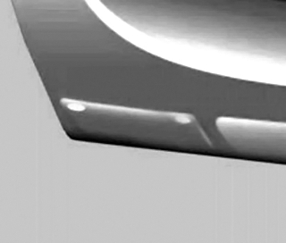
Diagram (version 1)
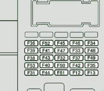
| № | A | Allocation |
|---|---|---|
| 12 | 7.5 | Right-hand dipped beam headlamp |
| 13 | 7.5 | Left-hand dipped beam headlamp - Headlamp height adjuster |
| 31 | 7.5 | Relay supply |
| 32 | 10 | Minibus interior lighting - Hazard warning lamps |
| 33 | 15 | Rear 12 V socket |
| 34 | - | Not used |
| 35 | 7.5 | Reversing lamps - Water in Diesel sensor |
| 36 | 15 | Door locking/unlocking unit |
| 37 | 7.5 | Brake lamps switch - Third brake lamp - Instrument panel |
| 38 | 10 | Interior relays |
| 39 | 10 | Audio equipment - Diagnostic socket - Alarm siren - Programmable additional heating controls |
| 40 | 15 | Defrosting: rear screen (left-hand side), mirror (passenger side) |
| 41 | 15 | Defrosting: rear screen (right-hand side), mirror (driver's side) |
| 42 | 7.5 | ABS control unit and sensor - ESP sensor - Brake lamps switch |
| 43 | 30 | Windscreen wiper motor |
| 44 | 20 | Cigar lighter - Front 12 V socket |
| 45 | 7.5 | Electric window and mirror switches (driver’s side) - Passenger electric window |
| 46 | - | Not used |
| 47 | 20 | Driver’s electric window motor |
| 48 | 20 | Passenger electric window motor |
| 49 | 7.5 | Rain/sunshine sensor - Audio equipment - Driver's electric window motor - Alarm - Instrument panel controls |
| 50 | 7.5 | Airbags and pre-tensioners unit |
| 51 | 7.5 | Tachograph - Cruise control - Air conditioning controls |
| 52 | 7.5 | Passenger compartment relays |
| 53 | 7.5 | Instrument panel - Rear fog amps |
Advertisements
Diagram (version 2)
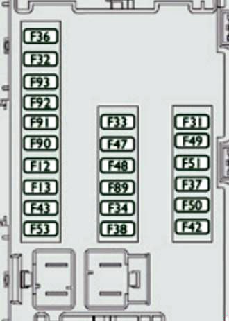
| № | A | Allocation |
|---|---|---|
| 12 | 7.5 | Right-hand dipped beam headlamp |
| 13 | 7.5 | Left-hand dipped beam headlamp |
| 31 | 5 | Relay supply |
| 32 | 7.5 | Interior lighting |
| 33 | 20 | Battery sensor |
| 34 | 20 | Minibus interior lighting - Hazard warning |
| 36 | 10 | Audio system - Diagnostic socket - Alarm siren - Programmable additional heating controls - Air conditioning controls - Tachograph - Battery |
| 37 | 7.5 | Brake lamps switch - Third brake lamp - Instrument panel |
| 38 | 20 | Central locking |
| 42 | 5 | ABS control unit and sensor - ASR sensor - ESP sensor - Brake lamps switch |
| 43 | 20 | Windscreen wiper motor |
| 47 | 20 | Driver's electric window motor |
| 48 | 20 | Passenger electric window motor |
| 49 | 5 | Audio system - Instrument panel controls |
| 50 | 7.5 | Airbags and pre-tensioners unit |
| 51 | 5 | Tachograph - Cruise control - Air conditioning controls - Reversing lamps - water in Diesel sensor |
| 53 | 7.5 | Instrument panel |
| 89 | - | Not used |
| 90 | 7.5 | Left hand main beam headlamp |
| 91 | 7.5 | Right han main beam headlamp |
| 92 | 7.5 | Left hand foglamp |
| 93 | 7.5 | Right hand foglamp |
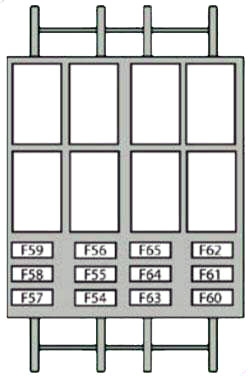
Door pillar Fuse Box
The fuses are located on the left-hand side door pillar.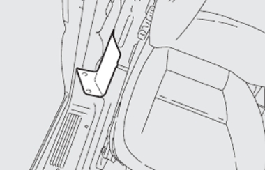
| № | A | Allocation |
|---|---|---|
| 54 | - | Not used |
| 55 | 15 | Heated seats |
| 56 | 15 | 12 V socket |
| 57 | 10 | Programmable additional heating |
| 57 | 10 | Ventilation/heating motor under the driver's seat |
| 58 | 15 | Demisting: left hand rear screen |
| 58 | 10 | Direction indicators |
| 59 | 15 | Demisting: right hand rear screen |
| 60 | - | Not used |
| 61 | - | Not used |
| 62 | - | Not used |
| 63 | 10 | Programmable additional heating switch |
| 64 | - | Not used |
| 65 | 30 | Programmable additional heating fan |
Advertisements
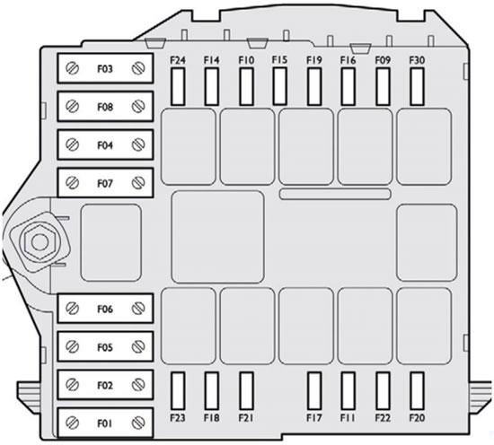
Fuses in the engine compartment
Remove the nuts and tilt the box to access the fuses.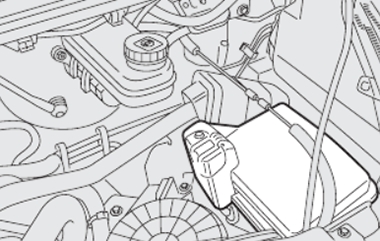
Version 1
| № | A | Allocation |
|---|---|---|
| 1 | 40 | ABS/ESP pump supply |
| 2 | 50 | Diesel pre-heat unit |
| 3 | 30 | Ignition switch |
| 4 | 20 | Programmable additional heating burner |
| 5 | 20 | Programmable additional heating controls relay |
| 6 | 40/60 | Fan assembly (high speed) |
| 7 | 40/50 | Fan assembly (low speed) |
| 8 | 40 | Air conditioning |
| 9 | 20 | Windscreen wash pump |
| 10 | 15 | Horn |
| 11 | 7.5 | Diesel pre-heat unit and relay |
| 14 | 7.5 | Right-hand main beam headlamp |
| 15 | 7.5 | Left-hand main beam headlamp |
| 16 | 7.5 | Engine control unit |
| 17 | 10 | Engine control unit |
| 18 | 7.5 | Engine control unit |
| 19 | 7.5 | Air conditioning compressor |
| 20 | 30 | Headlamp wash pump |
| 21 | 15 | Fuel pump supply |
| 22 | 20 | Engine control unit |
| 23 | 30 | ABS/ESP solenoid valves supply |
| 24 | - | Not used |
| 30 | 15 | Front fog lamps |
Advertisements
Version 2
| № | A | Allocation |
|---|---|---|
| 1 | 40 | ABS/ESP pump supply |
| 2 | 50 | Diesel pre-heater unit |
| 3 | 30 | Ignition switch |
| 4 | 30 | Headlamp washer pump |
| 8 | 40 | Cab fan unit |
| 9 | 15 | Rear 12 V socket |
| 10 | 15 | Horn |
| 14 | 15 | Front 12 V socket |
| 15 | 10 | Cigarette lighter |
| 20 | 30 | Screenwash pump |
| 21 | 15 | Fuel pump supply |
| 24 | 15 | Additional panel for ambulance - Mirrors |
| 30 | 15 | Demisting |
Advertisements