
Advertisements
Fuse box diagram (fuse layout), location and assignment of fuses and relays Chevrolet Orlando J309 (2011, 2012, 2013, 2014, 2015, 2016, 2017, 2018).

Checking and Replacing Fuses
The wiring circuits in the vehicle are protected from short circuits by a combination of fuses and circuit breakers. This greatly reduces the chance of damage caused by electrical problems.
To check a fuse, look at the silver-colored band inside the fuse. If the band is broken or melted, replace the fuse. Be sure to replace a bad fuse with a new one of the identical size and rating.
Fuses of the same amperage can be temporarily borrowed from another fuse location if a fuse goes out. Replace the fuse as soon as possible.
Note
- Before replacing a fuse check that the key has been removed from the ignition and that all the services are switched off and/or disengaged.
- Do not repair fuses and never replace a blown fuse with one that has a higher amp rating. This can cause damage to the electrical system and fire.
- Never replace a broken fuse with anything other than a new fuse. Use always an intact fuse of the same color.
- If a fuse blows again contact a qualified service center.
- Spilling liquid on any electrical component on the vehicle may damage it. Always keep the covers on any electrical component.
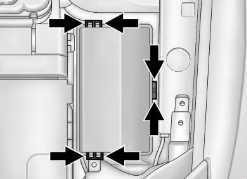
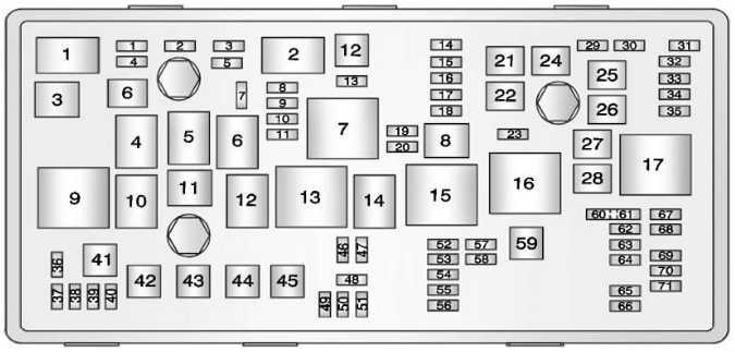
Engine Compartment Fuse Box
To remove the fuse block cover, squeeze the clips and lift it up.
| № | A | Description |
|---|---|---|
| 1 | 15 | Transmission Control Module |
| 2 | 15 | Engine Control Module |
| 3 | - | - |
| 5 | 15 | Transmission Control Module, Engine Control Module, Mass Air Flow/Intake Air Temperature Sensor, Output Speed Sensor |
| 6 | 30 | Windshield Wiper Relays |
| 7 | - | - |
| 8 | 15 | Fuel injectors |
| 9 | 15 | Ignition Coil, Fuel Injectors |
| 10 | 15 | Engine Control Module, Output Speed Sensor |
| 11 | 10 | Heated Oxygen Sensors |
| 12 | 30 | Starter Motor |
| 13 | 7.5 | Evaporative Emission (EVAP) Canister Vent Solenoid Valve |
| 14 | - | - |
| 15 | Rear Wiper | |
| 16 | 7.5 | Air Quality Sensor |
| 17 | 5 | Inflatable Restraint Sensing and Diagnostic Module |
| 18 | 10 | Fuel Pump Control Module |
| 19 | - | - |
| 20 | 20 | Fuel Pump Relay |
| 21 | 30 | Windows Motors, Front Door |
| 22 | - | - |
| 23 | - | - |
| 24 | 30 | Windows Motors, Front Door |
| 25 | Electronic Vacuum Pump | |
| 26 | 40 | Electronic Brake Control Module (EBCM) |
| 27 | 30 | Remote Control Door Lock Receiver |
| 28 | 40 | Rear Demister Grid |
| 29 | - | - |
| 30 | 15 | Electronic Brake Control Module (EBCM) |
| 31 | 20 | Body Control Module |
| 32 | 20 | Body Control Module |
| 33 | 30 | Heated Seat Control Module |
| 34 | 25 | Sunroof Control Module |
| 35 | 30 | Audio Amplifier |
| 36 | - | - |
| 37 | 10 | Headlamp - Right Main beam |
| 38 | 10 | Headlamp - Left Main beam |
| 39 | - | - |
| 40 | - | - |
| 41 | - | - |
| 42 | 20/30 | Cooling Fan Relays, Cooling Fan Motor |
| 43 | - | - |
| 44 | - | - |
| 45 | 30/40 | Cooling Fan High Speed Relay, Cooling Fan Motor |
| 46 | 10 | Cooling Fan Relays |
| 47 | 10 | Heated Oxygen Sensors, Throttle Body |
| 48 | 15 | Fog Lights, Front |
| 49 | - | - |
| 50 | - | - |
| 51 | 15 | Horn |
| 52 | 5 | Instrument Cluster |
| 53 | 10 | Inside Rearview Mirror |
| 54 | 5 | Headlamp Switch, Electrical Auxiliary Heater, HVAC Control Module |
| 55 | 7.5 | Window Switches, Front, Mirror Switch |
| 56 | 15 | Windscreen Washer Pump |
| 57 | 15 | Steering Column Lock Control Module |
| 58 | - | - |
| 59 | 30 | Fuel Heater |
| 60 | 7.5 | Outside Rearview Mirrors |
| 61 | Mirror Defogger | |
| 62 | 10 | A/C Compressor Clutch Relay, A/C Compressor Clutch |
| 63 | Rear Window Sensor | |
| 64 | 5 | Inflatable Restraint Sensing and Diagnostic Module |
| 65 | Rear Fog Lamp | |
| 66 | Rear Washer | |
| 67 | 20 | Fuel Pump Control Module |
| 68 | - | - |
| 69 | 5 | Body Control Module |
| 70 | 5 | Rain Sensor |
| 71 | - | - |
| 1 | A/C Compressor Clutch | |
| 2 | Starter | |
| 3 | Cooling Fan | |
| 4 | Windshield Wiper Speed Control | |
| 5 | Windshield Wiper | |
| 6 | - | |
| 7 | Powertrain | |
| 8 | Fuel Pump | |
| 9 | Cooling Fan Medium Speed 1 | |
| 10 | Cooling Fan Medium Speed 2 | |
| 11 | - | |
| 12 | Cooling Fan Speed Control (Or in Relay Block - Under-bonnet) | |
| 13 | Cooling Fan High Speed Relay | |
| 14 | - | |
| 15 | Ignition Main Relay | |
| 16 | Fuel Heater Relay | |
| 17 | Rear Window Defogger | |
| - | Horn Relay | |
| - | Windscreen Washer Pump Relay | |
| - | Front Fog Lamp Relay | |
| - | Headlamp High Beam Relay | |
Advertisements
Instrument Panel Fuse Block
Left-hand drive
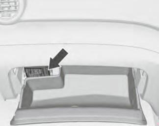
The instrument panel fuse block is on the driver side of the instrument panel.
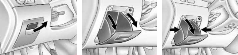
To access the fuses:
- Open the storage compartment by pulling out at the top.
- Squeeze the sides of the compartment in and rotate it downward.
- Remove the compartment.
- To reinstall the compartment, reverse the steps above.
Right-hand drive
The fuse box is behind the glove box.
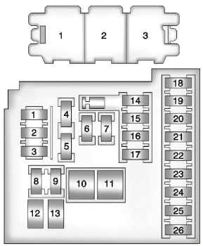
| № | A | Description |
|---|---|---|
| 1 | 10 | Mobile Telephone Control Module |
| 2 | - | DC/DC Converter |
| 3 | 25 | Body Control Module |
| 4 | 20 | Radio |
| 5 | 7.5 | Parking Assist Control Module, Power Sounder, Multifunction Switch - Centre Console, Display |
| 6 | 20 | Cigar Lighter |
| 7 | 20 | Power Outlet |
| 8 | 30 | Body Control Module |
| 9 | 30 | Body Control Module |
| 10 | 30 | Body Control Module |
| 11 | 40 | Blower Motor Control Module |
| 12 | - | - |
| 13 | 25 | Heated Seat Control Module |
| 14 | 7.5 | Data Link Connector, Oil Feeding Connector |
| 15 | 10 | Inflatable Restraint Sensing and Diagnostic Module |
| 16 | 10 | Rear Compartment Lid Release Relay |
| 17 | 15 | HVAC Control Module / HVAC Control Assembly |
| 18 | Trailer | |
| 19 | Battery Sensor | |
| 20 | - | - |
| 21 | 15 | Instrument Cluster |
| 22 | 2 | Ignition Switch |
| 23 | 20 | Body Control Module |
| 24 | 20 | Body Control Module |
| 25 | -- | - |
| 26 | 20 | Auxiliary Power Outlet |
| 1 | Tailgate Release Relay | |
| 2 | Logistic Mode Relay 1 | |
| 3 | Auxiliary Power Relay | |
Advertisements
Fuses above battery
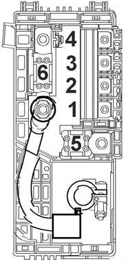
| № | A | Description |
|---|---|---|
| 1 | 100 | Fuse Block - Instrument Panel |
| 2 | 100 | Fuse Block - Instrument Panel |
| 3 | 80 | Electrical Power Steering (EPS) (NJ1) |
| 4 | - | - |
| 5 | 250 | Fuse Block - Battery Auxiliary |
| 6 | 250 / 500 | Starter Motor |
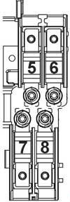
| № | A | Description |
|---|---|---|
| 5 | 80 | Glow Plug Control Module |
| 6 | 100 | Electrical Auxiliary Heater |
| 7 | - | - |
| 8 | - | - |
Relay Box
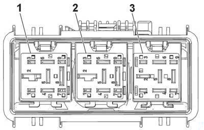
| № | Relays |
|---|---|
| 1 | Cooling Fan Left Medium Speed Relay |
| 2 | Cooling Fan Speed Control 2 Relay |
| 3 | Cooling Fan Right Medium Speed Relay |
Advertisements