
Advertisements
Fuse box diagram (fuse layout), location and assignment of fuses and relays of Cadillac Escalade and Escalade ESV (2014, 2015, 2016, 2017, 2018).

Checking and Replacing Fuses
The wiring circuits in the vehicle are protected from short circuits by fuses. This greatly reduces the chance of fires caused by electrical problems.
Look at the silver-colored band inside the fuse. If the band is broken or melted, replace the fuse. Be sure you replace a bad fuse with a new one of the identical size and rating.
Fuses of the same amperage can be temporarily borrowed from another fuse location if a fuse goes out. Replace the fuse as soon as you can.
Note
- Before replacing a fuse check that the key has been removed from the ignition and that all the services are switched off and/or disengaged.
- Do not repair fuses and never replace a blown fuse with one that has a higher amp rating. This can cause damage to the electrical system and fire.
- Never replace a broken fuse with anything other than a new fuse. Use always an intact fuse of the same color.
- If a fuse blows again contact authorized services
- Spilling liquid on any electrical component on the vehicle may damage it. Always keep the covers on any electrical component.
Engine Compartment Fuse Box Diagram
The fuse block is in the engine compartment, on the driver side of the vehicle. Lift the cover to access the fuses.
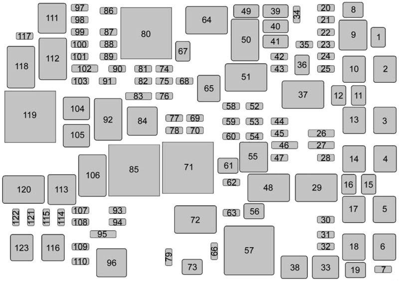
| № | Description |
|---|---|
| 1 | Electric running boards |
| 2 | Antilock brake system pump |
| 3 | Interior BEC LT1 |
| 4 | MBS passenger |
| 5 | Suspension leveling compressor |
| 6 | 4WD transfer case electronic control |
| 10 | Electric parking brake |
| 13 | Interior BEC LT2 |
| 14 | Rear BEC 1 |
| 17 | MBS driver |
| 21 | ALC exhaust solenoid |
| 23 | Integrated chassis control module |
| 24 | Real time dampening |
| 25 | Fuel pump power module |
| 26 | Spare/Battery regulated voltage control |
| 28 | Upfitter 2 |
| 29 | Upfitter 2 relay |
| 30 | Wiper |
| 31 | TIM |
| 34 | Back-up lamps |
| 35 | Antilock brake system valve |
| 36 | Trailer brakes |
| 37 | Upfitter 3 relay |
| 39 | Trailer stop, turn right |
| 40 | Trailer stop, turn left |
| 41 | Trailer park lamps |
| 42 | Right parking lamps |
| 43 | Left parking lamps |
| 44 | Upfitter 3 |
| 45 | Automatic level control run, crank |
| 47 | Upfitter 4 |
| 48 | Upfitter 4 relay |
| 49 | Reverse lamps |
| 51 | Parking lamp relay |
| 59 | Euro trailer |
| 60 | Air conditioning control |
| 63 | Upfitter 1 |
| 67 | Trailer battery |
| 69 | RC upfitter 3 and 4 |
| 70 | VBAT upfitter 3 and 4 |
| 72 | Upfitter 1 relay |
| 74 | Engine control module ignition |
| 75 | Miscellaneous ignition spare |
| 76 | Transmission ignition |
| 77 | RC upfitter 1 and 2 |
| 78 | VBAT upfitter 1 and 2 |
| 83 | Euro trailer RC |
| 84 | Run, crank relay |
| 87 | Engine |
| 88 | Injector A - odd |
| 89 | Injector B - even |
| 90 | Oxygen sensor B |
| 91 | Throttle control |
| 92 | Engine control module relay |
| 93 | Horn |
| 94 | Fog lamps |
| 95 | High-beam headlamps |
| 100 | Oxygen sensor A |
| 101 | Engine control module |
| 102 | Engine control module/ Transmission control module |
| 103 | Auxiliary interior heater |
| 104 | Starter |
| 107 | Aero shutter |
| 109 | Police upfitter |
| 112 | Starter relay |
| 114 | Front windshield washer |
| 115 | Rear window washer |
| 116 | Cooling fan left |
| 121 | Right HID headlamp |
| 122 | Left HID headlamp |
| 123 | Cooling fan right |
Advertisements
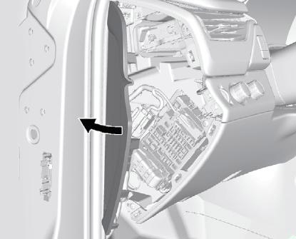
Left Instrument Panel Fuse Box
The fuse block access door is on the driver side edge of the instrument panel. Pull off the cover to access the fuse block.

| № | Description |
|---|---|
| 1 | - |
| 2 | - |
| 3 | - |
| 4 | Accessory power outlet 1 |
| 5 | Retained accessory power/Accessory |
| 6 | APO/BATT |
| 7 | Universal garage door opener/lnside rear view mirror |
| 8 | SEO retained accessory power |
| 9 | - |
| 10 | Body control module 3 |
| 11 | Body control module 5 |
| 12 | Steering wheel controls backlighting |
| 13 | - |
| 14 | - |
| 15 | - |
| 16 | Discrete logic ignition sensor |
| 17 | VPM |
| 18 | Mirror window module |
| 19 | Body control module 1 |
| 20 | Front bolster (if equipped) |
| 21 | - |
| 22 | - |
| 23 | - |
| 24 | Heater, ventilation and air conditioning ignition/Heater, ventilation and air conditioning auxiliary |
| 25 | Instrument cluster ignition/Sensing diagnostic module ignition |
| 26 | Tilt column/SEO, tilt column lock 1/SEO |
| 27 | Data link connector/ Driver seat module |
| 28 | Passive entry/Passive start/Heater, ventilation and air conditioning battery |
| 29 | Content theft |
| 30 | - |
| 31 | - |
| 32 | - |
| 33 | SEO/Automatic level control |
| 34 | Park enable electric adjustable pedal (if equipped) |
| 35 | - |
| 36 | Miscellaneous R/C |
| 37 | Heated steering wheel |
| 38 | Steering column lock 2 (if equipped) |
| 39 | Instrument cluster battery |
| 40 | - |
| 41 | - |
| 42 | Euro trailer (if equipped) |
| 43 | Left doors |
| 44 | Driver power seat |
| 45 | - |
| 46 | Right heated, cooled seat |
| 47 | Left heated, cooled seat |
| 48 | - |
| 49 | - |
| 50 | Accessory power outlet 2 |
| 51 | - |
| 52 | Retained accessory power/Accessory relay |
| 53 | Run, crank relay |
| 54 | - |
| 55 | - |
| 56 | - |
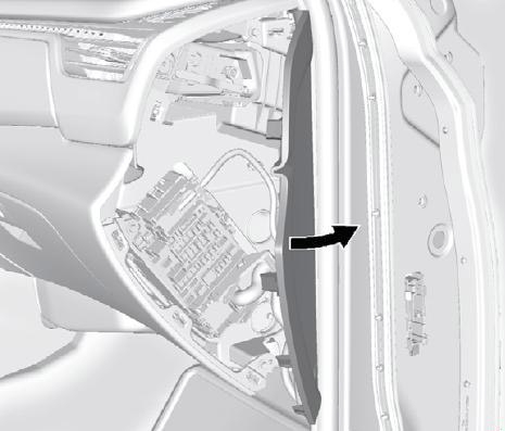
Right Instrument Panel Fuse Box
The fuse block access door is on the passenger side edge of the instrument panel. Pull off the cover to access the fuse block.
| № | Description |
|---|---|
| 1 | - |
| 2 | - |
| 3 | - |
| 4 | Accessory power outlet 4 |
| 5 | - |
| 6 | - |
| 7 | - |
| 8 | Glove box |
| 9 | - |
| 10 | - |
| 11 | - |
| 12 | Steering wheel controls |
| 13 | Body control module 8 |
| 14 | - |
| 15 | - |
| 16 | - |
| 17 | - |
| 18 | - |
| 19 | Body control module 4 |
| 20 | Rear seat entertainment |
| 21 | Sunroof |
| 22 | - |
| 23 | - |
| 24 | - |
| 25 | - |
| 26 | Info/Airbag |
| 27 | Spare/RF WDW RN SW |
| 28 | Obstacle detection/USB |
| 29 | Radio |
| 30 | - |
| 31 | - |
| 32 | - |
| 33 | - |
| 34 | - |
| 35 | - |
| 36 | SEO B2 |
| 37 | SEO |
| 38 | Body control module 2 |
| 39 | A/C Inverter |
| 40 | - |
| 41 | - |
| 42 | - |
| 43 | - |
| 44 | Right door window motor |
| 45 | Front blower |
| 46 | Body control module 6 |
| 47 | Body control module 7 |
| 48 | Amplifier |
| 49 | Right front seat |
| 50 | Accessory power outlet 3 |
| 51 | - |
| 52 | Retained accessory power/Accessory relay |
| 53 | - |
| 54 | - |
| 55 | - |
| 56 | - |
Advertisements
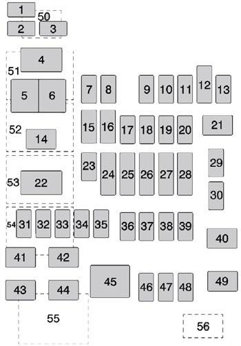
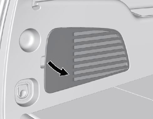
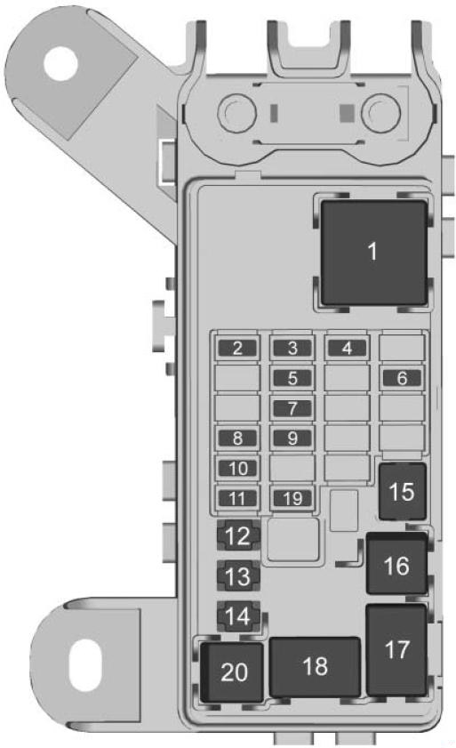
Rear Compartment Fuse Box
The fuse block is behind the access panel on the left side of the compartment. Pull the panel out by grabbing the finger access slot at the rear edge.
| № | Description |
|---|---|
| 1 | Rear defogger |
| 2 | Heated second row seat left |
| 3 | Heated second row seat right |
| 4 | Heated mirrors |
| 5 | Liftgate |
| 6 | Glass breakage |
| 7 | Liftglass |
| 8 | Liftgate module logic |
| 9 | Rear wiper |
| 10 | Rear heater, ventilation and air conditioning blower |
| 11 | Second row seat |
| 19 | Rear fog lamp (if equipped) |
| 12 | Liftgate module |
| 13 | Third row seat |
| 14 | Rear accessory power outlet |
| 15 | Rear defogger |
| 16 | Liftgate |
| 17 | Liftglass |
| 18 | Rear fog lamp (if equipped) |
| 20 | Heated mirrors |
Advertisements