
Advertisements
Fuse box diagrams (layout, location, function, assignment) in the cabin and engine compartment of Buick Regal (2011, 2012, 2013, 2014, 2015, 2016, 2017).
Checking and Replacing Fuses
The wiring circuits in the vehicle are protected from short circuits by a combination of fuses and circuit breakers. This greatly reduces the chance of damage caused by electrical problems.
To check a fuse, look at the silver-colored band inside the fuse. If the band is broken or melted, replace the fuse. Be sure to replace a bad fuse with a new one of the identical size and rating.
Fuses of the same amperage can be temporarily borrowed from another fuse location if a fuse goes out. Replace the fuse as soon as possible.
Warning!
- Do not repair fuses and never replace a blown fuse with one that has a higher amp rating. This can cause damage to the electrical system and fire.
- Spilling liquid on any electrical component on the vehicle may damage it. Always keep the covers on any electrical component.
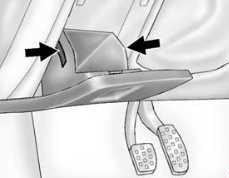
Instrument Panel Fuse Box Diagram
The instrument panel fuse block is located in the instrument panel, on the driver side of the vehicle. To access the fuses, open the storage compartment. Press in on the sides of the compartment to release it from the instrument panel. Pull the door toward you to release it from the hinge.
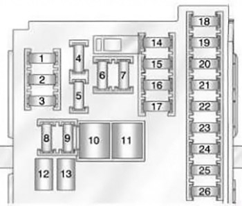
| № | Usage |
|---|---|
| 1 | Suspension Control Module/Universal Garage Door Opener/ESC |
| 2 | Body Control Module 1 |
| 3 | Body Control Module 5 |
| 4 | Radio |
| 5 | Radio Displays, Park Assist, Infotainment, Module Tunnel Control |
| 6 | Instrument Panel Power Outlet |
| 7 | Console Power Outlet |
| 8 | Body Control Module 3 |
| 9 | Body Control Module 4 |
| 10 | Body Control Module 8 |
| 11 | Front Heater Ventilation Air Conditioning/Blower |
| 12 | Right-Hand Power Front Seat |
| 13 | Left-Hand Power Front Seat |
| 14 | Diagnostic Link Connector |
| 15 | Airbag |
| 16 | Steering Wheel Controls |
| 17 | Heating Ventilation Air Conditioning Controller |
| 18 | Service Fuse, Logistic Relay |
| 19 | Memory Seats |
| 20 | Automatic Occupant Sensing |
| 21 | Instrument Cluster |
| 22 | Discrete Logic Ignition Switch/PEPS |
| 23 | Body Control Module 6 |
| 24 | Body Control Module 2 |
| 25 | OnStar |
| 26 | Spare |
Advertisements
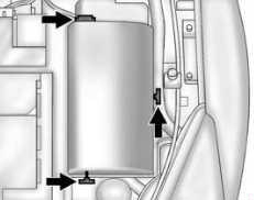
Engine Compartment Fuse Box Diagram
To remove the fuse block cover, press the three retaining clips on the cover and lift it straight up.
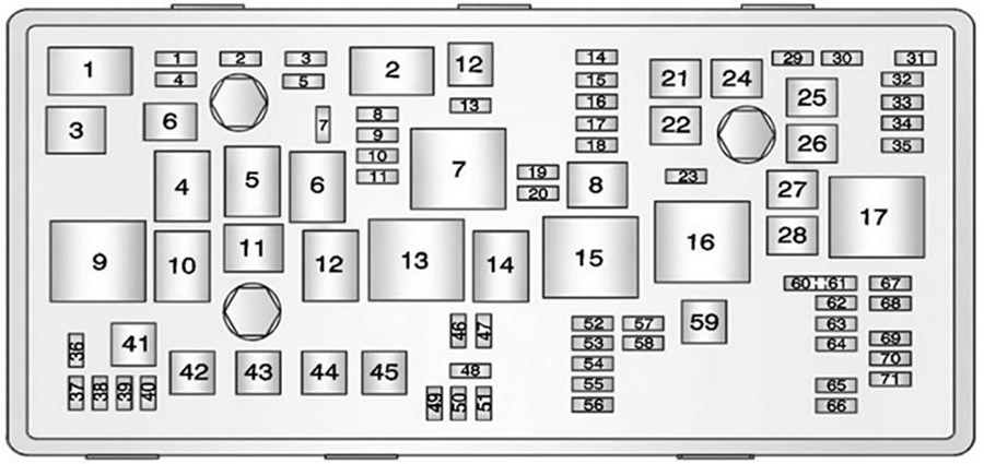
| № | Usage |
|---|---|
| 1 | Transmission Control Module |
| 2 | Engine Control Module |
| 3 | Not Used |
| 4 | Not Used |
| 5 | Ignition, Transmission Control Module, Engine Control Module |
| 6 | Windshield Wiper |
| 7 | BPIM (eAssist Only) |
| 8 | Not Used |
| 9 | Fuel Injection, Ignition System |
| 10 | Engine Control Module |
| 11 | Oxygen Sensor |
| 12 | Starter |
| 13 | Fuel System Control Module |
| 14 | Trunk Release |
| 15 | MGU Coolant Pump (eAssist Only) |
| 16 | Heated Steering Wheel |
| 17 | Not Used |
| 18 | BPIM (eAssist Only) |
| 19 | Not Used |
| 20 | Not Used |
| 21 | Rear Power Windows |
| 22 | Antilock Brake System Valve |
| 23 | Obstacle Detection |
| 24 | Front Power Windows |
| 25 | Power Outlets |
| 26 | Antilock Brake System Pump |
| 27 | Electric Parking Brake |
| 28 | Heated Rear Window |
| 29 | Left-Hand Seat Lumbar |
| 30 | Right-Hand Seat Lumbar |
| 31 | A/C Clutch |
| 32 | Body Control Module 6 |
| 33 | Heated Front Seats |
| 34 | Sunroof |
| 35 | Infotainment System |
| 36 | Adaptive Cruise |
| 37 | Right-Hand High-Beam Headlamp |
| 38 | Left-Hand High-Beam Headlamp |
| 39 | All-Wheel Drive |
| 40 | Not Used |
| 41 | Vacuum Pump |
| 42 | Radiator Fan |
| 43 | Passive Entry/ Passive Start |
| 44 | Transmission Auxiliary Pump (eAssist Only) |
| 45 | Radiator Fan |
| 46 | Terminal 87, Main Relay |
| 47 | Oxygen Sensor |
| 48 | Fog Lamps |
| 49 | Right-Hand Low Beam, High Intensity Discharge Headlamp |
| 50 | Left-Hand Low Beam, High Intensity Discharge Headlamp |
| 51 | Horn |
| 52 | Motor Indicator Lamp |
| 53 | Inside Rearview Mirror |
| 54 | Rear Camera |
| 55 | Power Windows/ Mirrors |
| 56 | Windshield Washer |
| 57 | Not Used |
| 58 | Not Used |
| 59 | Secondary Air Induction (eAssist Only) |
| 60 | Heated Mirrors |
| 61 | Not Used |
| 62 | Canister Vent Solenoid |
| 63 | Not Used |
| 64 | Heater, Ventilation, and Air Conditioning Pump (eAssist Only) |
| 65 | Not Used |
| 66 | SAI Check Valve (eAssist Only) |
| 67 | Fuel System Control Module |
| 68 | Not Used |
| 69 | Battery Sensor |
| 70 | Right Low Beam Headlamp/DRL |
| 71 | Not Used |
| 1 | Air Conditioning Control |
| 2 | Starter |
| 3 | Not Used |
| 4 | Front Wiper (Step 2) |
| 5 | Front Wiper (Step 1, Interval) |
| 6 | Right Low Beam Headlamp/DRL |
| 7 | Main Relay |
| 8 | Auxiliary Heater Pump (eAssist Only) |
| 9 | Cooling Fan |
| 10 | Cooling Fan |
| 11 | Transmission Auxiliary Pump (eAssist Only) |
| 12 | Not Used |
| 13 | Cooling Fan |
| 14 | High Intensity Discharge Headlamp/Left Low Beam Headlamp/DRL |
| 15 | Ignition |
| 16 | Secondary AIR Pump (eAssist Only) |
| 17 | Window/Mirror Defog |
Advertisements