Advertisements
Fuse box diagrams (layout, location, function, assignment) in the cabin and engine compartment of Audi A3 and S3 (8V; 2012, 2013, 2014, 2015, 2016).

Checking and Replacing Fuses
Fuses that have blown will have metal strips that have burned through.
- Turn off the ignition and the failed electrical equipment;
- Check the following table to see which fuse belongs to the equipment;
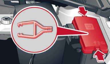
- Remove the cover;
- Remove the plastic clip from the fuse panel cover;
- Remove the blown fuse using the plastic clamp and replace the fuse with an identical new one;
- Install the cover.
Note
- If there are multiple fuse values in a cell in the following tables, for example, 5/10/20, it is because of equipment-related differences. Replace the burned fuse with an identical new one;
- If a new fuse should burn out again shortly after you have installed it, have the electrical system checked by your authorized Audi dealer or qualified repair facility as soon as possible;
- The following table does not list fuse locations that are not used;
- Some of the following tables only apply to certain models or options.
Warning!
Do not repair fuses and never replace a blown fuse with one that has a higher amp rating. This can cause damage to the electrical system and fire.
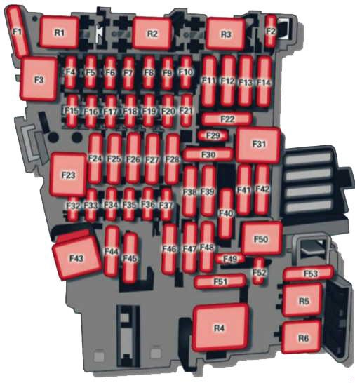
Instrument Panel Fuse Box Diagram
The fuses are behind the cover in the steering column area. Remove the cover (with “AIRBAG” label), begin at the bottom right corner.


| № | Equipment |
|---|---|
| 1 | Engine components |
| 2 | Seat adjustment |
| 3 | Hydraulic pump cover (Cabriolet) |
| 4 | MMI control panel, MMI components |
| 5 | Gateway |
| 6 | Selector lever (automatic transmission) |
| 7 | Climate/heating control, auxiliary heating, rear window defogger relay |
| 8 | Diagnosis, electromechanical parking brake switch, light switch, rain and light sensor, interior lighting communication box (Plug-in hybrid drive) anti-theft alarm system |
| 9 | Steering column switch module |
| 10 | Display |
| 11 | Reversible driver's side safety belt tensioners |
| 12 | MMI area |
| 13 | Adaptive dampers control module / service plug (Plug-in hybrid drive) |
| 14 | Climate control system blower |
| 15 | Electronic steering column lock |
| 16 | MMI area |
| 17 | Instrument cluster |
| 18 | Rearview camera |
| 19 | Convince key system control module, tank system |
| 20 | Tank system |
| 21 | - |
| 22 | - |
| 23 | Exterior lighting, heated washer fluid nozzles |
| 24 | Panorama sunroof / power top control module, power top latch (Cabriolet) |
| 25 | Door/driver's side doors (for example power windows) |
| 26 | Seat heating |
| 27 | Sound-amplifier |
| 28 | Power top control module, electronics (Cabriolet) |
| 29 | Interior lights |
| 30 | - |
| 31 | Exterior lighting |
| 32 | Driver assistance systems |
| 33 | Airbag |
| 34 | Button illumination, coils for upper cabin heating relay (Cabriolet) and socket relay, interior sound, reversing light switch, temperature sensor |
| 35 | Function lighting, diagnosis, headlight range control system, air quality sensor, automatic dimming rearview mirror |
| 36 | Right cornering light / right LED-headlight |
| 37 | Left cornering light / left LED-headlight |
| 38 | High-voltage battery (Plug-in hybrid drive) |
| 39 | Door/front passenger's side doors (for example, power windows) |
| 40 | Sockets |
| 41 | Reversible front passenger's side safety belt tensioners |
| 42 | Central locking components, windshield washer system |
| 43 | Headlights, lighting |
| 44 | All wheel drive |
| 45 | - |
| 46 | - |
| 47 | Rear window wiper |
| 48 | Outer noise amplifier (Plug-in hybrid drive) |
| 49 | Starter, clutch sensor, headlight relay coil, high-voltage battery (Plug-in hybrid drive) |
| 50 | - |
| 51 | - |
| 52 | - |
| 53 | Rear window defogger |
Advertisements
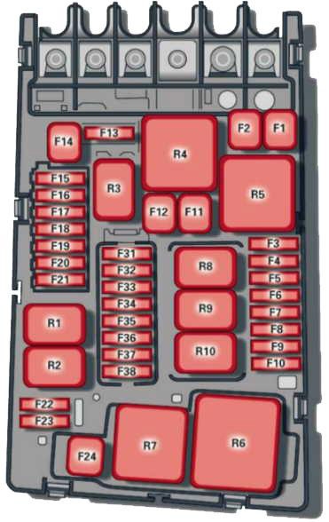
Engine Compartment Fuse Box Diagram


| № | Equipment |
|---|---|
| 1 | ESC control module |
| 2 | ESC control module |
| 3 | Engine control module (gasoline/diesel) |
| 4 | Engine cooling, engine components, auxiliary heater coil relay (1+2), secondary air injection pump relay |
| 5 | Engine components, tank system |
| 6 | Brake light sensor |
| 7 | Engine components, water pumps |
| 8 | Oxygen sensor |
| 9 | Engine components, exhaust door, glow time control module, SULEV valve |
| 10 | Fuel injectors, fuel control module |
| 11 | Auxiliary heater heating element 2 |
| 12 | Auxiliary heater heating element 3 |
| 13 | Automatic transmission control module |
| 14 | - |
| 15 | Horn |
| 16 | Ignition coil/power electronics (Plug-in hybrid drive) |
| 17 | ESC control module, engine control module |
| 18 | Terminal 30 (reference voltage) |
| 19 | Windshield wipers |
| 20 | Horn |
| 21 | - |
| 22 | Terminal 50 diagnosis |
| 23 | Starter |
| 24 | Auxiliary heater heating element 1, brake booster (Plug-in hybrid drive) |
| 25 | - |
| 26 | - |
| 27 | - |
| 28 | - |
| 29 | - |
| 30 | - |
| 31 | Vacuum pump/water pump (Plug-in hybrid drive) |
| 32 | LED headlights |
| 33 | Brake booster memory (Plug-in hybrid drive) |
| 34 | Brake booster control (Plug-in hybrid drive) |
| 35 | Relay (Plug-in hybrid drive) |
Advertisements
