Advertisements
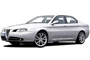
Checking and Replacing Fuses
The fuse is a protective device for the electric system: it comes into action (i.e. it cuts off) mainly due to a fault or improper action on the system. When a device does not work, check the efficiency of its fuse. The conductor element must be intact; if not, replace the fuse with one of the same amp rating (same colour).
Note
- Before replacing a fuse, make sure the ignition key has been removed and that all the other services are switched off and/or disengaged.
- Never replace a damaged fuse with anything other than an intact fuse.
- Never replace a fuse with another with a higher amp rating; DANGER OF FIRE.
- If a fuse blows again, contact an Alfa Romeo Authorised Service.
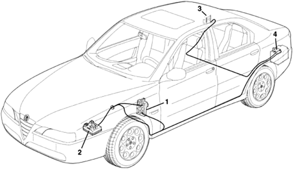
This model is fitted with three junction units: one (1) located underneath the dashboard to the left of the steering column, one (2) located in the engine compartment and a third (3) in the boot. In addition, the power supplies coming from the battery are protected by MAXIFUSES located on the actual battery (4).
Passenger Compartment Fuse Box Diagram
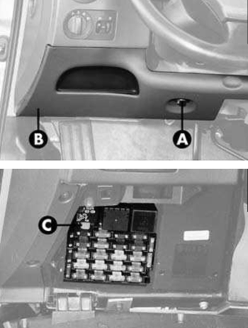
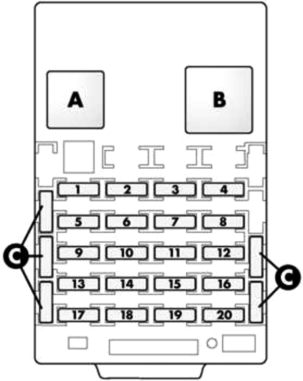
The fuses for the main devices are located in a control unit under the dashboard, to the left of the steering column. Access to it is gained slackening the knob (A) and lowering the panel (B). In the upper part of the control unit there is a pincer (C) for removing fuses.
| № | A | Function |
|---|---|---|
| 1 | 15 | Brake Lights, IGE Control Unit, Brake Depressed Light Control Signal, Control Panel, Direction Indicators (Steering Column Switch Unit), Exterior Lights Control |
| 2 | 10 | Air Bag Control Unit, Gearshift Lever |
| 3 | 5 | Sun Roof, Rear Socket, Seats |
| 4 | 15 | Radio |
| 5 | 10 | Mobile Phone, Glove Compartment Light, Cruise Control, Gear Lever Panel (CAE), Light Dimmer, Door Opening Receiver, Heated, Fold-Down Door Mirrors, Antitheft Control Unit, Switch On Console (C.M.), Compressor Relay Coil, Symbols (Switches/Buttons), I.C.S. System, Sound System Controls on Steering Wheel |
| 6 | 7.5 | Control Panel, Control Lighting, Headlights and Headlight Position Sensor (Gas Discharge Headlights), I.C.S. System |
| 7 | 10 | Front Current Socket (Cigar Lighter), I.C.S. System |
| 8 | 10 | Direction Indicators and Hazard Warning Lights, Right Side Lights |
| 9 | 5 | Control Lighting, Brake Lights Switch, IGE Control Unit, ABS |
| 10 | 5 | CAE Control Unit, Electronic Automatic Gearbox (Control Unit, Sensors and Gearshift Lever) |
| 11 | 15 | IGE Control Unit, Headlight Spot |
| 12 | 20 | Headlamp Washer |
| 13 | 10 | Sun Roof, ABI Control Unit, Electronic Automatic Gearbox, Reversing Lights (only Versions with Manual Gearbox) |
| 14 | 25 | Windscreen Wash/Wiper |
| 15 | 10 | IGE Control Unit, Rear Light Units |
| 16 | 5 | Alfa Romeo Code System, Electronic Injection System, Engine Cooling Control Unit, Compressor Relay, Electronic Automatic Gearbox, Fuel Pump Relay Coil (Engine Bay Box) |
| 17 | 10 | IGE Control Unit, Left Side Lights |
| 18 | 5 | Instrument Panel, I.C.S. System, Preparation for Mobile Phone, EOBD System (Diagnostic Socket), Navigator |
| 19 | 5 | Climate Control System Control Unit |
| 20 | 5 | Alfa Romeo Code System- Injection (Petrol) |
| C | Spare fuses | |
| A | Ignition Discharge | |
| B | Headlamp Washer Intermittent | |
Advertisements
Engine Compartment Fuse Box Diagram
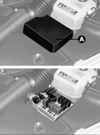
The fuses and relays in the engine bay are housed:
- In a box set next to the left side panel;
- On a bracket set behind the left headlight.
To gain access to the box, remove the cover (A), releasing it from the retaining clips.
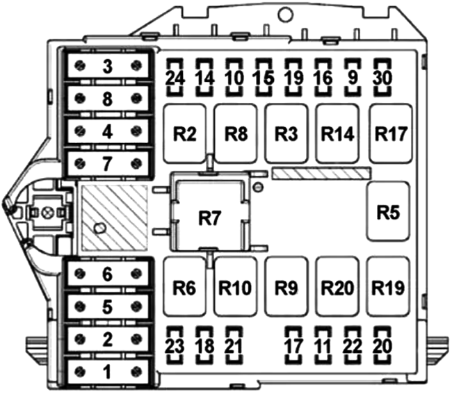
| № | A | Function |
|---|---|---|
| 1 | 50 | JTD: Glow Plugs |
| 60 | JTD: Glow Plugs | |
| 2 | 40 | ABS |
| 3 | 20 | Ignition Switch |
| 30 | Starter Motor | |
| 4 | 40 | ABS |
| 5 | 10 | CAE Ignition Lock |
| 20 | Electronic Automatic Gearbox (3.0 V6 24V Sportronic Version) | |
| 6 | 30 | Engine Cooling Fan (Low Speed) |
| 40 | Engine Cooling Fan (Low Speed) | |
| 7 | 60 | Engine Cooling Fan (High Speed) |
| 8 | 30 | Climate Control Fan |
| 9 | 15 | Electronic Automatic Gearbox - Sportronic Versions (Control Unit, Sensors and Gearshift Lever) |
| 10 | 15 | Horns |
| 11 | 15 | Electronic Injection Control Unit, Various Auxiliary Services I.E., Diesel Filter (JTD) |
| 14 | 15 | Right Main Beam Headlamp |
| 15 | 15 | Left Main Beam Headlamp, Headlamp Alignment |
| 16 | - | - |
| 17 | 10 | Electronic Injection Control Unit |
| 18 | 7.5 | Engine Control Unit, I.E. Services, CAE |
| 19 | 7.5 | Conditioner Compressor |
| 20 | 30 | JTD: Diesel Filter Heating |
| 21 | 15 | Fuel Pump |
| 22 | 20 | Electronic Injection Control Unit |
| 23 | 20 | JTD: Additional Heater |
| 24 | - | - |
| 30 | 15 | Front Fog Lights |
| R2 | High Beam | |
| R3 | Horn | |
| R5 | Compressor | |
| R6 | Radiator Fan 1st Speed | |
| R7 | Radiator Fan 2st Speed | |
| R8 | Climate Control System | |
| R9 | Fuel Injection Main | |
| R10 | Fuel Pump | |
| R14 | Fog Lamp | |
| R17 | CAE | |
| R19 | Heated Diesel Filter | |
| R20 | Starter Inhibitor | |
Additional Relays (JTD)
To gain access to relays on the bracket set behind the left headlight, remove the cover (A) after turning the fastening pins (B).
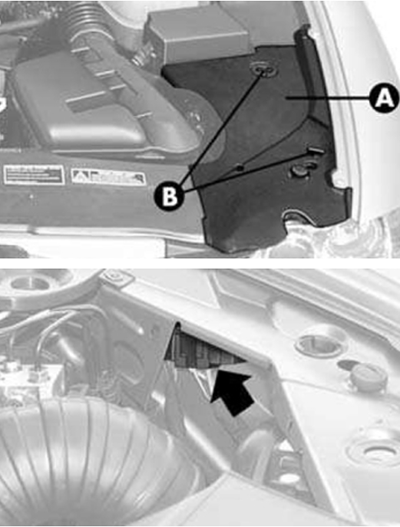
- Brown Relay: Additional Heater;
- Black Relay: Engine Cooling Radiator (High Speed).
Advertisements
Luggage Compartment Fuse Box Diagram
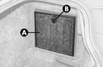
Fuses and relays are housed in the right-hand side of the boot are housed in a box, in the recess closed by cover (A). To open the cover turn the knob (B).
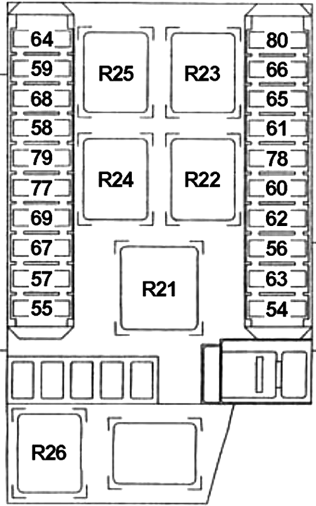
| № | A | Function |
|---|---|---|
| 54 | 25 | HIFI Amplifier |
| 55 | 20 | Sun-Roof |
| 56 | 20 | Driver's (LH) Side Front Window |
| 57 | 10 | Driver's (LH) Heated Seat |
| 58 | - | - |
| 59 | 7.5 | Mirror Demist |
| 60 | 20 | Passenger (RH) Side Front Window |
| 20 | Rear Current Socket | |
| 61 | 20 | Left Rear Electric Window |
| 62 | 20 | Right Rear Electric Window |
| 63 | 20 | Central Locking, Boot Release |
| 64 | 30 | Heated Rear Window |
| 65 | 10 | JTD: Additional Heater |
| 66 | 10 | Anti-Theft Device and Light Blinker, Diretction Indicators, Trailer Presetting |
| 67 | 10 | Passenger (RH) Heated Seat |
| 68 | 15 | Windscreen Demisting |
| 20 | Passenger (RH) Side Front Window | |
| 69 | 20 | Rear Current Socket |
| 15 | Windscreen Heating | |
| 77 | 30 | Driver's (LH) Seat Movement |
| 78 | 10 | Interior Lights, Rain Sensor, Mirror Adjustment, Seat Warming Control Light, Sun Vision Lights, Alarm System Control Unit, Electrochromic Driving Mirror, Parking Sensors Control Unit, Remote Control Receiver |
| 79 | 30 | Passenger (RH) Seat Movement |
| 80 | - | - |
| R21 | Sun Roof, Rear Socket | |
| R22 | Windscreen and Mirror Demisting | |
| R23 | Heated Rear Window | |
| R24 | Ignition Discharge | |
| R25 | Climate Control System Control Unit | |
| R26 | Lights Blinker | |
Maxi-Fuses
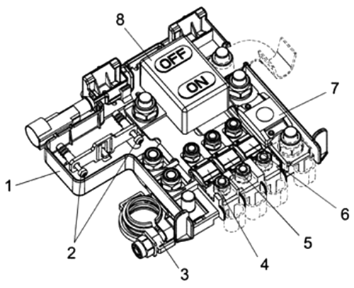
| № | A | Function |
|---|---|---|
| 4 | 70 | CPL |
| 5 | 70 | CVB |
| 6 | - | |
| 7 | 150 | CVM |
Advertisements
