Advertisements
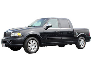
Fuse box diagram (fuse layout), location, and assignment of fuses and relays Lincoln Blackwood (Pickup Truck) (2001, 2002, 2003).

Checking and Replacing Fuses
Fuses and circuit breakers protect your vehicle’s electrical system from overloading. If electrical components in the vehicle are not working, a fuse may have blown. Check the appropriate fuses before replacing any electrical components.
Look carefully at the fuse – a broken wire within the fuse identifies blown fuses. If you are not sure or if it is too dark to see, try replacing the suspected fuse with one of the same value that you know is good.
In case if you do not have a spare fuse, in an emergency you can pull out fuses, which may be dispensable for normal driving (for example, audio system, cigarette lighter, OBD, seat heater, and the like), and use it if its amperage rating is the same.
Notice
- Always switch off the ignition system and the affected electrical circuit before replacing a fuse.
- Always disconnect the battery before servicing high current fuses.
- Never use a fuse of a higher amperage rating than that indicated, or use any other object in place of a fuse, even as a temporary fix. This can cause extensive damage or even fire.
- If the replaced fuses blows again – contact a qualified and equipped service center.
Passenger Compartment Fuse Box Diagram
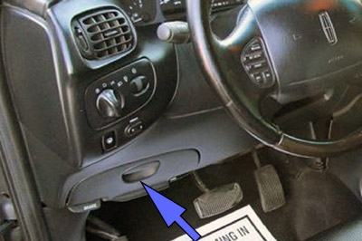
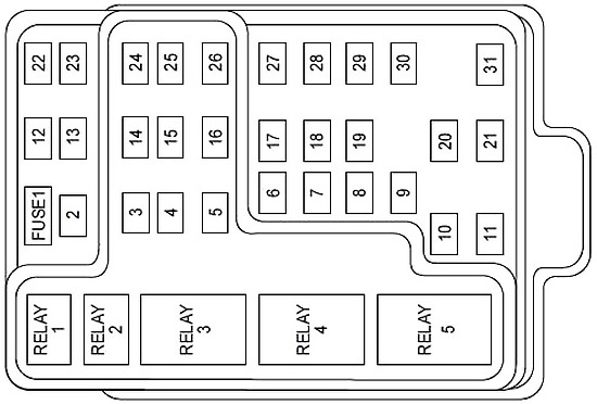
The fuse panel is located below and to the left of the steering wheel by the brake pedal. Remove the panel cover to access the fuses. To remove a fuse use the fuse puller tool provided on the fuse panel cover.


| № | A | Protected components |
|---|---|---|
| 1 | 25 | Radio, Amplifier, I/P fuse 31 |
| 2 | 5 | Powertrain Control Module (PCM), Instrument cluster, Electronic Automatic Temperature Control (EATC), Overhead Trip Computer Module (OTC), Navigation module, Clock |
| 3 | 20 | Cigar lighter, Data Link Connector (DLC) |
| 4 | 7.5 | Mirrors, Seats, Pedals, (memory) |
| 5 | 15 | Speed control module, Reverse lamp, Reverse Sensing System (RSS), E/C mirror, Central security module, Navigation module |
| 6 | 5 | Cluster, Brake shift interlock solenoid, Generic Electronic Module (GEM), RSS, Air suspension, OTC, Compass, Automatic parking brake release |
| 7 | 5 | Console blower relay |
| 8 | 5 | E/C mirror, Navigation module, Clock, GEM |
| 9 | - | - |
| 10 | - | - |
| 11 | 30 | Front washer pump relay, Wiper Run/Park relay, Wiper Hi/Lo relay, Windshield wiper motor |
| 12 | 15 | Air suspension |
| 13 | 20 | Stop lamp switch (lamps), Turn/Hazard flasher, Trailer brake, Radio Frequency Interference (RFI) module |
| 14 | 15 | Battery saver relay, Interior lamp relay, Accessory delay relay (power windows) |
| 15 | 5 | Stop lamp switch, (speed control, brake shift interlock, Anti-lock Brake System (ABS), PCM module inputs, Traction control, Air suspension, Central security Module, GEM |
| 16 | 20 | Headlamps (Hi Beams), Cluster (Hi Beam Indicator) |
| 17 | 10 | Heated mirrors, Rear defrost |
| 18 | 5 | Instrument illumination (dimmer switch power) |
| 19 | - | - |
| 20 | 5 | GEM, Power tonneau cover, Air suspension, Memory |
| 21 | 15 | Starter relay, Fuse 20 of the fuse panel, Radio |
| 22 | 10 | Air bag module |
| 23 | 10 | Trailer tow battery charge relay, Turn/Hazard flasher, Rear console controls, Climate control seats, Traction control module |
| 24 | 10 | I/P fuse 7, EATC, Blower relay |
| 25 | - | - |
| 26 | 10 | Right side low beam headlamp |
| 27 | 5 | Fog lamp relay and fog lamp indicator |
| 28 | 10 | Left side low beam headlamp |
| 29 | 5 | Autolamp module, Transmission overdrive control switch, Central security module, Power tonneau |
| 30 | 30 | Passive anti-theft transceiver, Instrument cluster, Ignition coils, PCM Relay |
| 31 | 10 | CD changer, Rear console controls |
| R1 | Interior lamp | |
| R2 | Battery saver | |
| R3 | Heated grid | |
| R4 | One touch down window | |
| R5 | Ignition key accessory delay | |
Advertisements
Engine Compartment Fuse Box Diagram
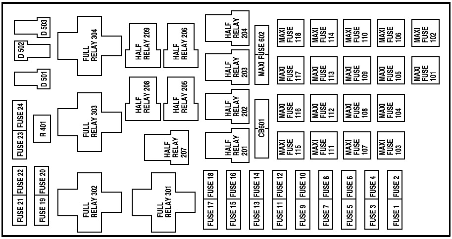
The power distribution box is located in the engine compartment. The power distribution box contains high-current fuses that protect your vehicle’s main electrical systems from overloads.

| № | A | Protected components |
|---|---|---|
| 1 | 20 | Power point |
| 2 | 30 | Powertrain control module (PCM) |
| 3 | 30 | Headlamps/Autolamps |
| 4 | 20 | Console power point |
| 5 | 20 | Trailer tow back-up/park lamps |
| 6 | 15 | Parklamps/Autolamps, Passenger fuse panel feed fuse #18 |
| 7 | 20 | Horn |
| 8 | 30 | Power door locks |
| 9 | 15 | Fog lamps, Power tonneau |
| 10 | 20 | Fuel pump |
| 11 | 20 | Alternator field |
| 12 | 20 | Rear auxiliary power point |
| 13 | 15 | A/C clutch |
| 14 | 20 | Box power point |
| 15 | - | - |
| 16 | - | - |
| 17 | 10 | Delayed accessory |
| 18 | 15 | PCM, Fuel Injectors, Fuel pump relay, Idle Air control, Mass air flow sensor |
| 19 | 10 | Trailer tow stop and right turn lamp |
| 20 | 10 | Trailer tow stop and left turn lamp |
| 21 | - | - |
| 22 | - | - |
| 23 | 15 | HEGO sensor, Canister vent, Automatic transmission, CMS sensor |
| 24 | - | - |
| 101 | 30 | Trailer tow battery charge |
| 102 | 50 | Anti-lock Brake System (ABS) module, Traction control |
| 103 | 50 | Junction block battery feed |
| 104 | - | - |
| 105 | 40 | Climate control front blower |
| 106 | - | - |
| 107 | 30 | Passenger power seat |
| 108 | 30 | Trailer tow electric brake |
| 109 | 50 | Air suspension |
| 110 | 30 | Climate control seats |
| 111 | 40 | Ignition switch battery feed (start and run circuits) |
| 112 | 30 | Drivers power seat, Adjustable pedals |
| 113 | 40 | Ignition switch battery feed (run and accessory circuits) |
| 114 | - | - |
| 115 | - | - |
| 116 | 40 | Heated grid/mirrors |
| 117 | - | - |
| 118 | - | - |
| 602 | 50 | Power tonneau |
| 201 | Trailer tow park lamp | |
| 202 | Front wiper run/park | |
| 203 | Trailer tow backup lamp | |
| 204 | A/C clutch | |
| 205 | - | |
| 206 | Fog lamp | |
| 207 | Front washer pump | |
| 208 | - | |
| 209 | - | |
| 301 | Fuel pump | |
| 302 | Trailer tow battery charge | |
| 303 | Wiper high/low | |
| 304 | PCM | |
| 401 | - | |
| 501 | PCM | |
| 502 | A/C compressor | |
| 503 | Auto park brake | |
| 601 | 30 | Power windows, Moonroof |
Advertisements
