Advertisements
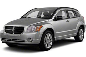
Fuse box diagram (fuse layout), location and assignment of fuses and relays Dodge Caliber (2007, 2008, 2009, 2010, 2011, 2012).

Checking and Replacing Fuses
The wiring circuits in the vehicle are protected from short circuits by fuses. This greatly reduces the chance of damage caused by electrical problems.
To check a fuse, look at the silver-colored band inside the fuse. If the band is broken or melted, replace the fuse. Be sure to replace a bad fuse with a new one of the identical size and rating.
Fuses of the same amperage can be temporarily borrowed from another fuse location if a fuse goes out. Replace the fuse as soon as possible.
Caution
- Before replacing a fuse check that the key has been removed from the ignition and that all the services are switched off and/or disengaged.
- When installing the Integrated Power Module cover, it is important to ensure the cover is properly positioned and fully latched. Failure to do so may allow water to get into the Integrated Power Module, and possibly result in an electrical system failure.
- When replacing a blown fuse, it is important to use only a fuse having the correct amperage rating. The use of a fuse with a rating other than indicated may result in a dangerous electrical system overload. If a properly rated fuse continues to blow, it indicates a problem in the circuit that must be corrected.
Engine Compartment Fuse Box Diagram
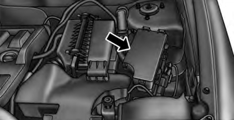
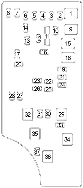
An Integrated Power Module is located in the engine compartment near the air cleaner assembly. This center contains cartridge fuses and mini fuses. A label that identifies each component may be printed on the inside of the cover.


| № | A | Protected Component |
|---|---|---|
| 1 | - | - |
| 2 | 20 | All Wheel Drive Control Module (4WD/AWD) |
| 3 | 10 | Stop Lamp Switch |
| 4 | 10 | Ignition Switch, Sentry Key Remote Entry Module, Engine Control Module, Totally Integrated Power Module (TIPM) |
| 5 | - | - |
| 6 | 10 | Occupant Classification Module, Left Vanity Lamp, Hands Free Module, Satellite Receiver, Mirror Switch |
| 7 | 30 | Fuse: "14", "20", "21" |
| 8 | 30 | Fuse: "6", "17", "19" |
| 9 | - | - |
| 10 | 20 | Cluster |
| 11 | - | - |
| 12 | 20 | Inverter Module |
| 13 | 20 | Dome Lamp |
| 14 | 10 | Cluster |
| 15 | 50 | Radiator Fan (Low/High) Relay, Radiator Fan (Medium/High) Relay |
| 16 | 15 | Power Outlet (Instrument Panel), Power Outlet (AC), Sunroof, Rear Wiper |
| 17 | 10 | Transmission Control Module (CVT), Steering Control Module, Sentry Key Remote Entry Module |
| 18 | 40 | Main Relay (Fuse: "23", "26", "32") |
| 19 | 20 | Radio Amplifier, Subwoofer |
| 20 | 15 | Radio |
| 21 | 10 | Export: Intrusion Transceiver Module, Siren |
| 22 | 10 | A/C Heater Control, Compass |
| 23 | 15 | Gasoline: Ignition Coils, Ignition Capacitor |
| 15 | Diesel: Glow Plug Module, Valve Block Assembly, Mass Air Flow Sensor | |
| 24 | 25 | Sunroof Motor |
| 25 | 10 | Heated Mirror |
| 26 | 15 | Gasoline: Fuel Injectors, Camshaft Position Solenoid |
| 15 | Diesel: A/C Compressor Solenoid, EGR Air Flow Control Valve | |
| 27 | 10 | Occupant Restraint Controller Module (ORC) |
| 28 | 10 | Occupant Restraint Controller Module (ORC) |
| 29 | - | - |
| 30 | 20 | Heated Seats Module |
| 31 | 10 | Diesel: Cabin Heater Relay No.1, Cabin Heater Relay No.2 |
| 32 | 30 | Gasoline: Powertrain Control Module |
| 30 | Diesel: Engine Control Module | |
| 33 | 10 | Data Link Connector, Powertrain Control Module (Gasoline), Bank Switch, Main Relay, Radiator Fan (Low/High) Relay, Radiator Fan (Medium/High) Relay, Radiator Fan (Series/Parallel) Relay |
| 34 | 30 | ABS |
| 35 | 40 | ABS |
| 36 | - | - |
| 37 | - | - |
Advertisements
Additional Fuse Box

| № | A | Protected Component |
|---|---|---|
| 6 | 25 | Diesel: Cabin Heater Relay No.2 |
| 8 | 25 | Diesel: Cabin Heater Relay No.1 |
| 10 | 50 | Diesel: Glow Plug Module |
| R1 | Radiator Fan (Low/High) | |
| R2 | Radiator Fan (Series/Parallel) | |
| R3 | Radiator Fan (Medium/High) | |
| R4 | Main | |
| R5 | - | |
Advertisements
