Advertisements
Fuse box diagram (fuse layout), location, and assignment of fuses Chrysler Crossfire (2004, 2005, 2006, 2007, 2008).

Checking and Replacing Fuses
The wiring circuits in the vehicle are protected from short circuits by fuses. This greatly reduces the chance of damage caused by electrical problems.
To check a fuse, look at the silver-colored band inside the fuse. If the band is broken or melted, replace the fuse. Be sure to replace a bad fuse with a new one of the identical size and rating.
Fuses of the same amperage can be temporarily borrowed from another fuse location if a fuse goes out. Replace the fuse as soon as possible.
Note
- Before replacing a fuse check that the key has been removed from the ignition and that all the services are switched off and/or disengaged.
- Do not repair fuses and never replace a blown fuse with one that has a higher amp rating. This can cause damage to the electrical system and fire.
- If a fuse blows again contact a qualified service center.
Instrument Panel Fuse Box Diagram
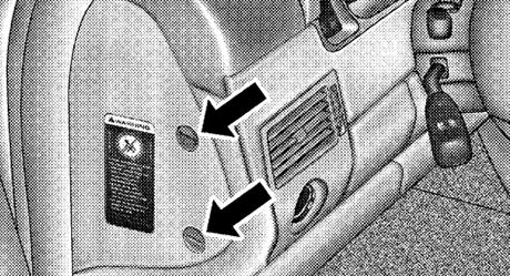
The fuse access door is located on the end of the instrument panel on the driver’s side behind the trim panel cover. Use a coin or flat blade screwdriver to open and close this access door.
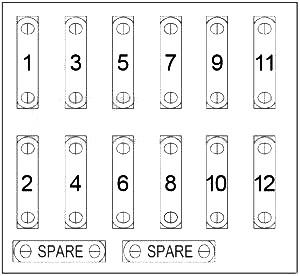
| № | A | Protected Component |
|---|---|---|
| 1 | - | - |
| 2 | 15 | Stop Lamp Switch, ABS, Stop Lamp Relay |
| 3 | 7.5 | Right High Beam, High Beam Indicator Lamp |
| 4 | 15 | Back-Up Lamp, Turn Signal Lamp, Automatic Day/Night Mirror, Radio |
| 5 | 7.5 | Left High Beam |
| 6 | 15 | Right Low Beam |
| 7 | 7.5 | Front Right Parking Light, Right Side Marker, Right Taillamp |
| 8 | 15 | Left Low Beam |
| 9 | 15 | Front Fog Lamp |
| 10 | 7.5 | Front Left Parking Light, Left Side Marker, Left Taillamp |
| 11 | 7.5 | License Lamp, Instrument Cluster, Ash Receiver |
| 12 | 7.5 | Rear Fog Lamp |
Advertisements
Engine Compartment Fuse Box
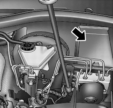
The underhood accessory fuse block fuses are located under the hood on the driver’s side, between the brake master cylinder and the left front fender. To remove the lid, squeeze the tabs together located at the front of the fusebox. Then lift the lid up by the tabs. The lid will then slide off the top of the fuse box. To replace the lid, place the two hinge-like tabs at the rear of the lid under the tabs on the fusebox. Push down on the front of the lid until the tabs at the front click.
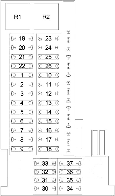
| № | A | Protected Component |
|---|---|---|
| 1 | 5 | Stop Lamp Switch, Garage Door Opener (Europe), Universal Garage Door Opener, Tire Pressure Monitor, Heated Seat Module |
| 2 | 5 | Occupant Restraint Controller, Passenger Seat Occupant Simulator, Left/Right Side Impact Sensor |
| 3 | 5 | Instrument Cluster, Airbag Off Indicator Lamp |
| 4 | 7.5 | Power Mirror |
| 5 | 15 | Radio |
| 25 | Convertible: Power Top Control Module | |
| 6 | 5 | Power Mirror Switch |
| 40 | Convertible: Power Top Hydraulic Assembly | |
| 7 | 5 | Body Control Module, Automatic Day/Night Mirror, Intrusion Sensor |
| 8 | 15 | Radio |
| 9 | 10 | Dome Lamp, Cargo Lamp, Siren, Anti-Theft Tow Sensor, Intrusion Sensor, Body Control Module, Universal Garage Door Opener, Tire Pressure Monitor |
| 10 | 5 | Speed Control Switch |
| 11 | 15 | Ignition Coils, Noise Suppressor |
| 12 | 10 | Heated Washer Nozzles |
| 13 | 10 | SRT: Charge Air Cooler Circulation Pump |
| 14 | 10 | Data Link Connector, Steering Angle Sensor |
| 15 | 5 | Coolant Circulation Pump, Coolant Circulation Valve |
| 16 | 10 | Body Control Module |
| 17 | 40 | ABS |
| 18 | 40 | ABS |
| 19 | 40 | Body Control Module |
| 20 | 40 | Body Control Module |
| 21 | 30 | RHD: Driver Power Seat |
| 30 | LHD: Passenger Power Seat | |
| 22 | 30 | RHD: Passenger Power Seat |
| 30 | LHD: Driver Power Seat | |
| 23 | 15 | Power Amplifier |
| 24 | 30 | Heated Seat Module |
| 25 | 20 | Central Locking Pump/Security System Module |
| 26 | 20 | Central Locking Pump/Security System Module |
| 30 | 15 | Convertible: Radio |
| 31 | 15 | Cigar Lighter, Glove Box Lamp |
| 32 | 15 | Multi-Function Switch |
| 33 | 5 | A/C Heater Control Module |
| 34 | 30 | Convertible: Blower Motor |
| 35 | 15 | Instrument Cluster, Remote Keyless Entry Relay, Console Switch Group, Key-In Ignition Switch, Sentry Key Remote Entry Module, A/C Heater Control Module |
| 36 | 30 | Blower Motor |
| 5 | Convertible: Power Mirror Switch | |
| 37 | 5 | A/C Heater Control Module, Recirculated Air Switchover Valve, Sentry Key Remote Entry Module, Instrument Cluster, Illumination Control Module, Ash Receiver Lamp, Power Window Switch, Power Top Switch, Console Switch Group, Radio |
| R1 | Stop Lamp | |
| R2 | Remote Keyless Entry | |
Advertisements
Relay Control Module
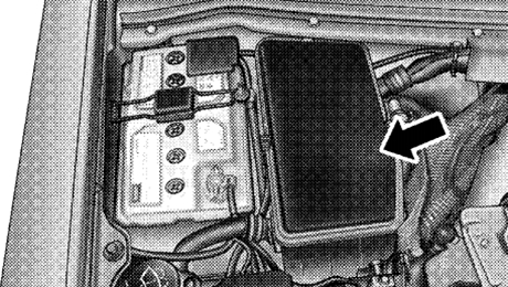
The relay control module fuses are located in the Control Module Box next to the battery in the engine compartment. Slide the control module box cover retaining clips forward and lift the cover from the control module box to gain access to the relay control module fuses.

| № | A | Protected Component |
|---|---|---|
| 1 | 15 | Traction System Relay |
| 2 | 15 | Oxygen Sensors, Air Pump Relay, EVAP Purge Solenoid, Charcoal Canister Shutoff Valve, Air Pump Switchover Solenoid, EGR Solenoid (except SRT), Supercharger Clutch (SRT), Short Runner Valve Solenoid (except SRT) |
| 3 | 15 | Powertrain Control Module, Fuel Injectors, Camshaft Position Sensor, Fuel Pump Relay |
| 4 | 40 | Air Pump Relay |
| 5 | 15 | Fuel Pump Relay |
| 6 | 15 | Horn Relay |
Fusible Link Block
| № | A | Protected Component |
|---|---|---|
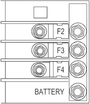
| F2 | 50 | Radiator Fan Control Module |
| F3 | 50 | ABS, Pulse Module |
| F4 | 200 | Main |
Advertisements
