
Advertisements
Fuse box diagram (fuse layout), location and assignment of fuses and relays Chevrolet Equinox mk2 (2010, 2011, 2012, 2013, 2014, 2015, 2016, 2017).

Checking and Replacing Fuses
The wiring circuits in the vehicle are protected from short circuits by fuses. This greatly reduces the chance of damage caused by electrical problems.
Look at the silver-colored band inside the fuse. If the band is broken or melted, replace the fuse. Be sure to replace a bad fuse with a new one of the identical size and rating.
Replace a bad fuse with a new one of the identical size and rating.
If there is a problem on the road and a fuse needs to be replaced, the same amperage fuse can be borrowed. Choose some features of the vehicle that is not needed to use and replace it as soon as possible.
Note
- Before replacing a fuse check that the key has been removed from the ignition and that all the services are switched off and/or disengaged.
- Do not repair fuses and never replace a blown fuse with one that has a higher amp rating. This can cause damage to the electrical system and fire.
- Never replace a broken fuse with anything other than a new fuse. Use always an intact fuse of the same color.
- If a fuse blows again contact a qualified service center.
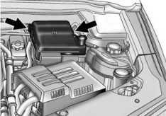
There are two fuse blocks in the vehicle: one in the engine compartment and one in the instrument panel. There is a fuse puller located in the engine compartment fuse block. It can be used to easily remove fuses from the fuse block.
Engine Compartment Fuse Box Diagram
To remove the fuse block cover, squeeze the clips on the cover and lift it straight up.
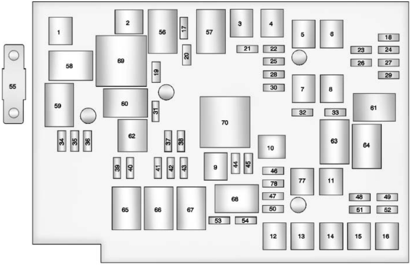
| № | Usage |
|---|---|
| 1 | Cool Fan 1 |
| 2 | Cool Fan 2 |
| 3 | Brake Booster |
| 4 | Power Windows -Right |
| 5 | Memory Seat Module |
| 6 | Power Seat - Left |
| 7 | Instrument Panel Fuse Block 1 |
| 8 | Rear Defogger |
| 9 | Starter |
| 10 | AIR Pump Motor |
| 11 | Instrument Panel Fuse Block 2 |
| 12 | Sunroof |
| 13 | Antilock Brake System Pump |
| 14 | Instrument Panel Fuse Block 3 |
| 15 | Power Windows - Left |
| 16 | Antilock Brake System Module |
| 17 | Transmission Control Module Battery |
| 18 | Trailer Parking Light |
| 19 | AIR Pump Solenoid |
| 20 | Engine Control Module Battery |
| 21 | Canister Vent |
| 22 | Trailer Left Side (If Equipped) |
| 23 | Lift Gate Module |
| 24 | Power Lumbar |
| 25 | Trailer Right Side (If Equipped) |
| 26 | Rear Accessory Power Outlet |
| 27 | Memory Mirror Module |
| 28 | Regulated Voltage Control Battery Sensor |
| 29 | Front Wiper |
| 30 | Rear Wiper |
| 31 | Air Conditioning Compressor |
| 32 | Rear Latch |
| 33 | Heated Mirrors |
| 34 | Horn |
| 35 | Right High-Beam Headlamp |
| 36 | Left High-Beam Headlamp |
| 37 | Ignition Even Coil |
| 38 | Ignition Odd Coil |
| 39 | Windshield Washer |
| 40 | Front Fog Lamps |
| 41 | Post Catalytic Converter Oxygen Sensor |
| 42 | Engine Control Module |
| 43 | Pre-Catalytic Converter Oxygen Sensor |
| 44 | Transmission Control Module |
| 45 | Mirror |
| 46 | Fuel System Control Module Ignition |
| 47 | Spare |
| 48 | Rear Drive Module |
| 49 | Lift Gate Module Logic |
| 50 | Instrument Panel Fuse Block Ignition |
| 51 | Heated Seat- Front |
| 52 | Fuel System Control Module |
| 53 | Engine Control Module |
| 54 | Rear Vision Camera |
| 55 | Electric Power Steering |
| 56 | AIR Pump Solenoid |
| 57 | Brake Booster |
| 58 | Cooling Fan Low |
| 59 | Headlamp High Beam |
| 60 | Cooling Fan Control |
| 61 | Wiper On/Off Control |
| 62 | Air Conditioning Compressor |
| 63 | Rear Defogger |
| 64 | Wiper Speed |
| 65 | Fog Lamp |
| 66 | Engine Control |
| 67 | Starter |
| 68 | Run/Crank |
| 69 | Cooling Fan High |
| 70 | AIR Pump Motor |
| 77 | Power Seat - Right |
| 78 | Passenger Power Lumber |
Advertisements
Instrument Panel Fuse Box Diagram
The instrument panel fuse block is located on the passenger side panel of the center console. To access the fuses, open the fuse panel door from the passenger side by pulling it out.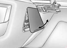
To reinstall the door, insert the tabs on the top of the door into the console first, then push the door back into its original location.
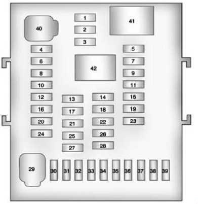
| № | Usage |
|---|---|
| 1 | Steering Wheel Dimming |
| 2 | Spare |
| 3 | Spare |
| 4 | Body Control Module 1 |
| 5 | Infotainment |
| 6 | Body Control Module 7 |
| 7 | Noise Control Module |
| 8 | Body Control Module 4 |
| 9 | Radio |
| 10 | Spare |
| 11 | Rear Parking Assist Module |
| 12 | Heater, Ventilation, and Air Conditioning Battery |
| 13 | Auxiliary Power Front |
| 14 | Heater, Ventilation and Air Conditioning Ignition |
| 15 | Display |
| 16 | Body Control Module 5 |
| 17 | Auxiliary Power Rear |
| 18 | Instrument Panel Ignition |
| 19 | Universal Garage Door Opener |
| 20 | Body Control Module 6 |
| 21 | Spare |
| 22 | Sensing and Diagnostic Module Ignition |
| 23 | Front Camera |
| 24 | Spare |
| 25 | Transmission Gear Shift Position Indicator |
| 26 | Spare |
| 27 | Spare |
| 28 | Spare |
| 29 | Front Blower Motor |
| 30 | Body Control Module 3 |
| 31 | Amplifier |
| 32 | Discrete Logic Ignition Switch |
| 33 | Communications Integration Module |
| 34 | Body Control Module 2 |
| 35 | Sensing and Diagnostic Module Battery |
| 36 | Data Link Connection |
| 37 | Instrument Panel Battery |
| 38 | Passenger Sensing System Module |
| 39 | Spare |
| 40 | Body Control Module 8 |
| 41 | Logistic Relay (If Equipped) |
| 42 | Retained Accessory Power Relay |
Advertisements