Advertisements
Fuse box diagram (fuse layout), location, and assignment of fuses and relays Alfa Romeo GT (Type 937) (2003, 2004, 2005, 2006, 2007, 2008, 2009, 2010).
Checking and Replacing Fuses
The fuse is a protective device for the electric system: it comes into action (i.e. it cuts off) mainly due to a fault or improper action on the system. When a device does not work, check the efficiency of its fuse. The conductor element must be intact; if not, replace the fuse with one of the same amp rating (same colour).
Note
- Before replacing a fuse, make sure the ignition key has been removed and that all the other services are switched off and/or disengaged.
- Never replace a fuse with metal wires or anything else. Always use an intact fuse of the same colour.
- Never replace a fuse with another with a higher amp rating; DANGER OF FIRE.
- If a fuse blows again, contact an Alfa Romeo Authorised Service.
Passenger Compartment Fuse Box Diagram
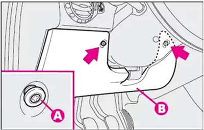
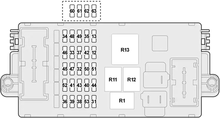
To gain access to the fuses in the fuse box on the dashboard, loosen the two retainers (A) and remove the protective cover (B).
| № | A | Description |
|---|---|---|
| 12 | 10 | Right Dipped-Beam Headlight |
| 13 | 10 | Left Dipped-Beam Headlight, Headlight Aiming Device |
| 31 | 7.5 | Climate Control System, Heater Unit Relay Coils |
| 32 | 15 | Selespeed Transmission, Key-Operated +30 |
| 33 | 20 | Rear Left Power Window |
| 34 | 20 | Rear Right Power Window |
| 35 | 7.5 | Reversing Light, Cruise Control, Climate Control System Control Lighting |
| 36 | 10 | Trailer Control Unit |
| 37 | 10 | Braking Light, Instrument Cluster |
| 38 | 20 | Central Door Locking |
| 39 | 15 | Climate Control System, Radio, Navigator, Services + 30, Volumetric Sensors, EOBD System Diagnosis Socket, Cell Phone Provision, Driver’s Door Control Unit, Boot Control Unit |
| 40 | 30 | Rearscreen Heating |
| 41 | 7.5 | Heated Mirrors, Heated Nozzles |
| 42 | 7.5 | VDC System Sensor, Steering Angle Sensor, ABS Control Unit |
| 43 | 30 | Windscreen, Rearscreen Washer (Two-Way Pump) |
| 44 | 20 | Cigar Lighter |
| 45 | 15 | Heated Seats |
| 46 | 15 | Sunroof |
| 47 | 20 | Driver’s Door Control Unit Supply |
| 48 | 20 | Passenger’s Door Control Unit Supply |
| 49 | 7.5 | Secondary Services, Control Lighting |
| 50 | 7.5 | Air Bag Control Unit |
| 51 | 7.5 | Selespeed Transmission |
| 52 | - | - |
| 53 | 10 | Hazard Lights, +30 Direction Indicators, Instrument Cluster |
| 60 | 25 | - |
| 61 | 15 | - |
| 62 | 15 | Electric Windows Controlunits |
| 63 | 20 | - |
Advertisements
Engine Compartment Fuse Box Diagram
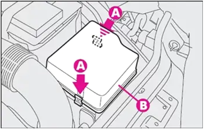
Access is gained to the control box next to the battery releasing the perimetral catches (A) and removing the protective cover (B).
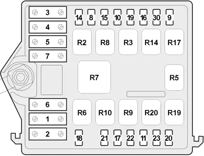
| № | A | Description |
|---|---|---|
| 1 | 50 | Diesel: Glow Plug Preheating |
| 2 | 50 | Dashboard Control Unit |
| 3 | 30 | Selespeed Transmission Pump |
| 4 | 50/60 | ABS Control Unit |
| 5 | 40 | Climate control fan |
| 6 | 40 | Diesel: Radiator Fan (First Speed) |
| 30 | Petrol: Radiator Fan (First Speed) | |
| 7 | 50 | Petrol: Radiator Fan (Second Speed) |
| 60 | Diesel: Radiator Fan (Second Speed) | |
| 8 | 30 | Additional Heater (PTC) |
| 9 | 20 | Headlight Washer |
| 10 | 15 | Horn |
| 11 | 15 | Secondary Services (Electronic Injection) |
| 14 | 10 | Right Main-Beam Headlight |
| 15 | 10 | Left Main-Beam Headlight |
| 16 | 7.5 | Electronic Injection System |
| 17 | 7.5 | Primary Services (Electronic Injection) |
| 18 | 7.5 | Electronic Injection Control Unit (+30) |
| 19 | 7.5 | Climate Control Compressor |
| 20 | 20 | Diesel: Heated Fuel Oil Filter |
| 21 | 15 | Fuel Pump, Ignition Coils |
| 22 | 15 | Petrol: Injectors |
| 20 | Diesel: Injectors | |
| 23 | - | - |
| 30 | 15 | Fog Lights |
| 10 | Fog Lights | |
| R2 | High Beam | |
| R3 | Horn | |
| R5 | Compressor | |
| R6 | Radiator Fan 1st Speed | |
| R7 | Radiator Fan 2st Speed | |
| R8 | Additional Heater (PTC) | |
| R9 | Fuel Injection Main | |
| R10 | Fuel Pump | |
| R14 | Fog Lamp | |
| R17 | Headlamp Washer | |
| R19 | Diesel: Heated Fuel Oil Filter | |
| R20 | - | |
Engine Compartment Fuse Box №2 (only 3.2L)
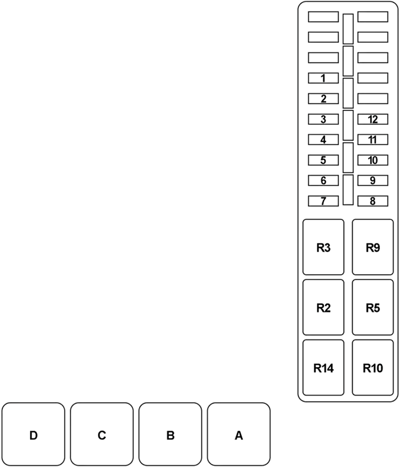
| № | A | Description |
|---|---|---|
| 1 | 7.5 | Compressor |
| 2 | 15 | High Beam |
| 3 | 15 | Horn |
| 4 | 15 | Fuel Pump |
| 5 | 20 | Headlight Washer |
| 6 | 7.5 | Electronic Injection System |
| 7 | 15 | Fog Lights |
| 8 | 7.5 | Primary Services (Electronic Injection) |
| 9 | 15 | Secondary Services (Electronic Injection) |
| 10 | 15 | Coils, Injectors |
| 11 | 7.5 | 15/54 |
| 12 | 7.5 | Electronic Injection System (15/54) |
| R2 | High Beam | |
| R3 | Horn | |
| R5 | Compressor | |
| R9 | Injectors | |
| R10 | Fuel Pump | |
| R14 | Fog Lights | |
| A | Radiator Fan Relay №1 | |
| B | Radiator Fan Relay №2 | |
| C | Radiator Fan Relay №2 | |
| D | Selespeed Pump | |
Control Box on Battery Positive Pole
To gain access to the fuses on the battery post, remove the protective cover pressing the opening catches (front).
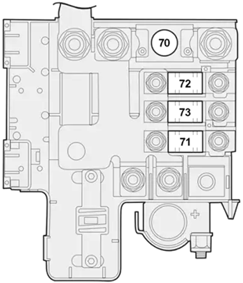
| № | A | Description |
|---|---|---|
| 70 | 125 | Petrol: Engine Compartment Control Box |
| 150 | Diesel: Engine Compartment Control Box | |
| 71 | 70 | Dashboard Control Unit |
| 72 | 30 | Ignition Switch |
| 73 | 30 | Additional Heater |
Advertisements
