
Advertisements
Fuse box diagram (fuse layout), location, and assignment of fuses and relays Toyota 86, GT86, FT86 (2012, 2013, 2014, 2015, 2016, 2017, 2018).

Checking and Replacing Fuses
The fuses are designed to blow before the entire wiring harness is damaged. If any of the electrical components do not operate, a fuse may have blown. If this happens, check and replace the fuses as necessary.
- Turn the engine switch off (with a smart key system – turn the “ENGINE START STOP” switch off) and turn off all electrical accessories.
- Open the fuse box cover.
- See diagrams below for details about which fuse to check.
- Remove the fuse.
- Check if the fuse is blown – if the thin wire inside is broken, the fuse has blown.
- Replace the blown fuse with a new fuse of an appropriate amperage rating.
Notice
- Never use a fuse of a higher amperage rating than that indicated, or use any other object in place of a fuse, even as a temporary fix. This can cause extensive damage or even fire.
- Always use a genuine Toyota fuse or equivalent.
- Do not modify the fuses or fuse boxes.
- If the replaced fuse blows again, have the vehicle inspected by any authorized Toyota dealer or repairer, or another duly qualified and equipped professional.
Passenger Compartment
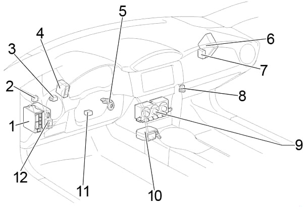
Left-hand drive
Right-hand drive
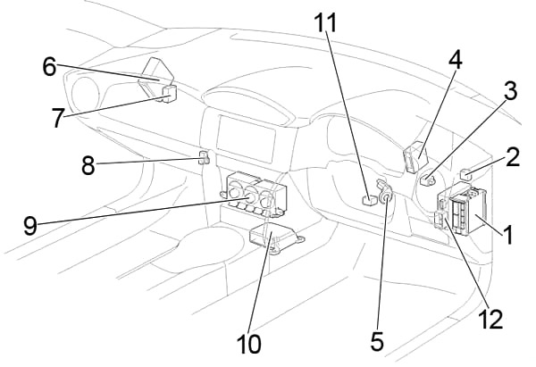
- Fuse Box / Main Body ECU
- Headlight Leveling ECU
- Turn Signal Flasher
- Transmission Control ECU
- Transponder Key Amplifier
- ECM
- Control Unit Relay
- Relay Box
- A/C Control
- Airbag ECU
- Steering Lock Actuator
- Power Steering ECU
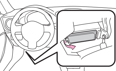
Passenger Compartment Fuse Box
The fuse panel is located below the driver’s side of the dashboard. Remove the lid to access the fuses.
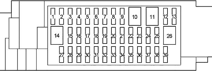
Relay Box:
| № | Fuse | A | Circuit |
|---|---|---|---|
| 1 | P/POINT №1 | 15 | Power outlet |
| 2 | RADIO | 7.5 | Audio system |
| 3 | SEAT HTR RH | 10 | Right-hand seat heater |
| 4 | SEAT HTR LH | 10 | Left-hand seat heater |
| 5 | ECU IG2 | 10 | Engine control unit |
| 6 | GAUGE | 7.5 | Gauge and meters |
| 7 | AT UNIT | 15 | Transmission |
| 8 | - | - | - |
| 9 | - | - | - |
| 10 | - | - | - |
| 11 | - | - | - |
| 12 | - | - | - |
| 13 | AMP | 15 | Audio system |
| 14 | - | - | - |
| 15 | AM1 | 7.5 | Starting system |
| 16 | - | - | - |
| 17 | - | - | - |
| 18 | - | - | - |
| 19 | - | - | - |
| 20 | ECU IG1 | 10 | ABS, electric power steering |
| 21 | BK/UP LP | 7.5 | Back-up lights |
| 22 | FR FOG RH | 10 | Right-hand front fog light |
| 23 | FR FOG LH | 10 | Left-hand front fog light |
| 24 | HEATER | 10 | Air conditioning system |
| 25 | HEATER-S | 7.5 | Air conditioning system |
| 26 | - | - | - |
| 27 | OBD | 7.5 | On-board diagnosis system |
| 28 | - | - | - |
| 29 | - | - | - |
| 30 | STOP | 7.5 | Stop lights |
| 31 | - | - | - |
| 32 | - | - | - |
| 33 | - | - | - |
| 34 | DRL | 10 | Daytime running light system |
| 35 | - | - | - |
| 36 | TAIL | 10 | Tail lights |
| 37 | PANEL | 10 | Illumination |
| 38 | P/POINT №2 | 15 | Power outlet |
| 39 | ECU ACC | 10 | Main body ECU, outside rear view mirrors |
| 1 | - | - | - |
| R1 | Blower Motor | ||
Advertisements
Engine Compartment

- Fuse Box
- LHD: Fusible Link Block
- RHD: Fusible Link Block
- Brake Actuator
- Headlight Cleaner Control Relay
- Injector Driver (EDU)
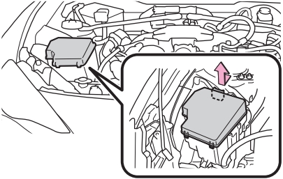
Engine Compartment Fuse Box
Push the tabs in and lift the lid off.
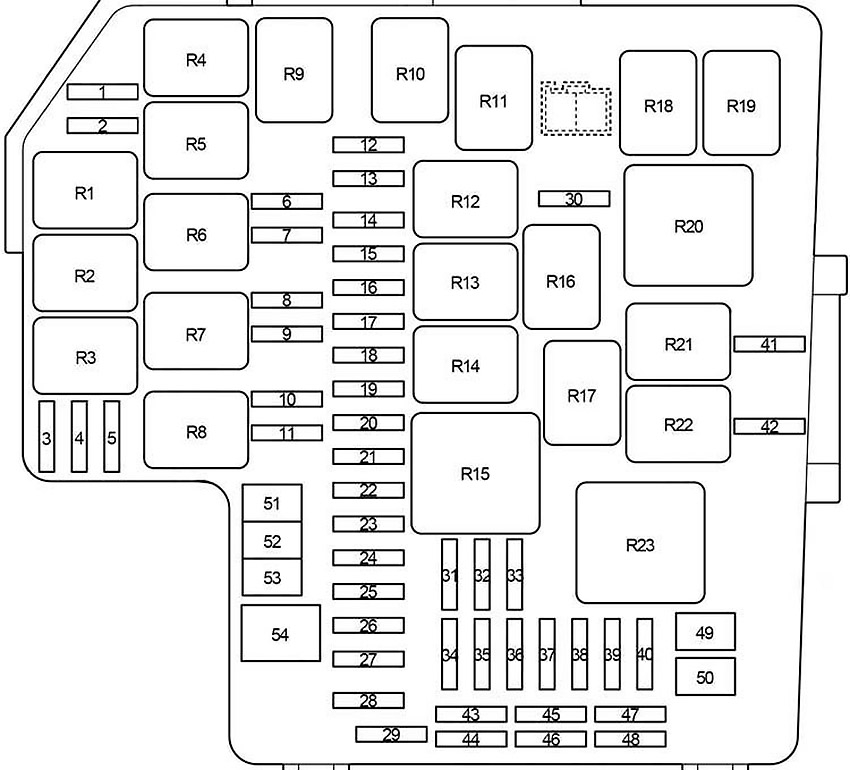
| № | Fuse | A | Circuit |
|---|---|---|---|
| 1 | A/B MAIN | 15 | SRS airbag system |
| 2 | - | - | - |
| 3 | IG2 | 7.5 | Engine control unit |
| 4 | DOME | 20 | Interior light |
| 5 | ECU-B | 7.5 | Wireless remote control, main body ECU |
| 6 | HORN №2 | 7.5 | Horn |
| 7 | HORN №1 | 7.5 | Horn |
| 8 | H-LP LH LO | 15 | Left-hand headlight (low beam) |
| 9 | H-LP RH LO | 15 | Right-hand headlight (low beam) |
| 10 | H-LP LH HI | 10 | Left-hand headlight (high beam) |
| 11 | H-LP RH HI | 10 | Right-hand headlight (high beam) |
| 12 | ST | 7.5 | Starting system |
| 13 | ALT-S | 7.5 | Charging system |
| 14 | STR LOCK | 7.5 | Steering lock system |
| 15 | D/L | 20 | Power door lock |
| 16 | ETCS | 15 | Engine control unit |
| 17 | AT+B | 7.5 | Transmission |
| 18 | AM2 №2 | 7.5 | Smart entry & start system |
| 19 | - | - | - |
| 20 | EFI (CTRL) | 15 | Engine control unit |
| 21 | EFI (HTR) | 15 | Multiport fuel injection system/sequential multiport fuel injection system |
| 22 | EFI (IGN) | 15 | Starting system |
| 23 | EFI (+B) | 7.5 | Engine control unit |
| 24 | HAZ | 15 | Turn signal lights, emergency flashers |
| 25 | MPX-B | 7.5 | Automatic air conditioning system, gauge and meters |
| 26 | F/PMP | 20 | Multiport fuel injection system/sequential multiport fuel injection system |
| 27 | IG2 MAIN | 30 | SRS airbag system, engine control unit |
| 28 | DCC | 30 | "ECU-B", "DOME" fuses |
| 29 | - | - | - |
| 30 | PUSH-AT | 7.5 | Engine control unit |
| 31 | - | - | - |
| 32 | WIPER | 30 | Windshield wipers |
| 33 | WASHER | 10 | Windshield washer |
| 34 | D FL DOOR | 25 | Power window |
| 35 | ABS №2 | 25 | ABS |
| 36 | D-OP | 25 | - |
| 37 | CDS | 25 | Electric cooling fan |
| 38 | D FR DOOR | 25 | Power window |
| 39 | RR FOG | 10 | Rear fog light |
| 40 | RR DEF | 30 | Rear window defogger |
| 41 | MIR HTR | 7.5 | Outside rear view mirror defoggers |
| 42 | RDI | 25 | Electric cooling fan |
| 43 | - | - | Spare fuse |
| 44 | - | - | Spare fuse |
| 45 | - | - | Spare fuse |
| 46 | - | - | Spare fuse |
| 47 | - | - | Spare fuse |
| 48 | - | - | Spare fuse |
| 49 | ABS №1 | 40 | ABS |
| 50 | HEATER | 50 | Air conditioning system |
| 51 | INJ | 30 | Multiport fuel injection system/sequential multiport fuel injection system |
| 52 | H-LP WASHER | 30 | Headlight cleaners |
| 53 | AM2 №1 | 40 | Starting system, engine control unit |
| 54 | EPS | 80 | Electric power steering |
| R1 | (EFI MAIN1) | ||
| R2 | Electric cooling fan (FAN №3) | ||
| R3 | Heater | ||
| R4 | (EFI MAIN3) | ||
| R5 | (ETCS) | ||
| R6 | Horn | ||
| R7 | (H-LP) | ||
| R8 | Dimmer (DIM) | ||
| R9 | (EFI MAIN2) | ||
| R10 | Fuel pump (C/OPEN) | ||
| R11 | Inhibitor | ||
| R12 | with Front Marker Light: (DRL RH) | ||
| without Front Marker Light: Daytime running light system (DRL) | |||
| R13 | Starter (ST CUT) | ||
| R14 | (IGS) | ||
| R15 | Rear window defogger (RR DEF) | ||
| R16 | Starter (ST) | ||
| R17 | Ignition (IG2) | ||
| R18 | with Front Marker Light: (DRL LH) | ||
| without Front Marker Light: Rear fog light (RR FOG) | |||
| R19 | Electric cooling fan (FAN №2) | ||
| R20 | (INJ) | ||
| R21 | Outside rear view mirror defoggers (MIR HTR) | ||
| R22 | Electric cooling fan (FAN №1) | ||
| R23 | Windshield wipers (WIPER) | ||
Fusible Link Block
It is on the battery “+” terminal.
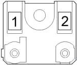
| № | Fuse | A | Circuit |
|---|---|---|---|
| 1 | ALT | 140 | Charging system |
| 2 | MAIN | 80 | Horn relay, headlight relay, dimmer relay, "ALT-S", "ETCS", "F/PMP", "MPX-B", "HAZ", "EFI (+B)", "EFI (IGN)", "EFI (HTR)", "EFI (CTRL)", "AT+B", "IG2 MAIN", "AM2 №2", "EPS", "INJ", "AM2 №1", "H-LP WASHER", "STR LOCK", "DCC", "D/L" fuses |
Advertisements