
Advertisements
Fuse box diagram (fuse layout), location, and assignment of fuses Skoda Octavia Mk1 / 1U (1996, 1997, 1998, 1999, 2000, 2001, 2002, 2003, 2004).
Checking and Replacing Fuses
Individual electrical circuits are protected by fuses.
- Before replacing a fuse, switch off the ignition and the appropriate consumer.
- Find out which fuse belongs to the component that is not operating.
- Defect fuses can be detected by their melted metal strips. Replace the defect fuse by a new fuse of the same ampere number.
- If a new fuse burns through again, consult a specialist immediately.
Notice
- Never “repair” fuses and also do not replace them with a fuse of a higher amperage – risk of fire! This may also cause damage at another part of the electrical system.
- Have the electrical system checked as quickly as possible by a ŠKODA specialist garage if a newly inserted fuse blows again after a short time.
- We recommend always carrying replacement fuses in the vehicle.
Passenger Compartment Fuse Box
The fuses are located on the left side of the dash panel behind the safety cover.
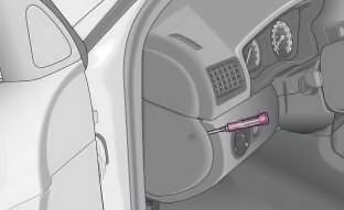
- Switch the ignition off and also the electrical component affected.
- Use a screwdriver to take off the fuse cover on the side of the dash panel.
- Find out which fuse belongs to the relevant component.
- Take the plastic clip out of its fixture in the fuse cover, insert it onto the respective fuse and pull out this fuse.
- Defect fuses can be detected by their melted metal strips. Replace the defect fuse by a new fuse of the same ampere number.
- Fit on the fuse cover again.
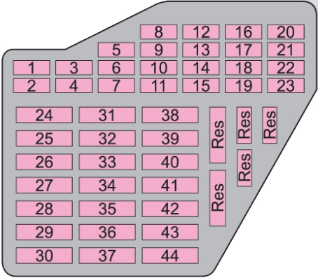
| № | Power consumer | A |
|---|---|---|
| 1 | Heating of the exterior mirrors, relay for cigarette lighter, power seats and washing nozzles | 10 |
| 2 | Turn signal lights, Xenon headlight | 10 |
| 3 | Lighting in storage compartment | 5 |
| 4 | Licence plate light | 5 |
| 5 | Seat heating, Climatronic, circulating air flap, exterior mirror heater, cruise control system | 7.5 |
| 6 | Central locking system | 5 |
| 7 | Reversing light, sensors for parking aid | 10 |
| 8 | Phone | 5 |
| 9 | ABS, ESP | 5 |
| 10 | Ignition, S-contact (*a) | 10 |
| 11 | Instrument cluster | 5 |
| 12 | Power supply of the self-diagnosis | 7.5 |
| 13 | Brake lights | 10 |
| 14 | Interior lighting, central locking system, interior lighting (without central locking system) | 10 |
| 15 | Instrument cluster, steering angle sender, rear mirror | 5 |
| 16 | Air conditioning system | 10 |
| 17 | Heated windscreen washer nozzles | 5 |
| Daylight driving lights | 30 | |
| 18 | Right main beam | 10 |
| 19 | Left main beam | 10 |
| 20 | Right low beam, headlight range adjustment | 15 |
| 21 | Low beam on the left | 15 |
| 22 | Right parking light | 5 |
| 23 | Left parking light | 5 |
| 24 | Front window wiper, motor for wash pump | 20 |
| 25 | Air blower, air conditioning system, Climatronic | 25 |
| 26 | Rear window heater | 25 |
| 27 | Rear window wiper | 15 |
| 28 | Fuel pump | 15 |
| 29 | Control unit: Petrol engine | 15 |
| Control unit: Diesel engine | 10 | |
| 30 | Electric sliding/tilting roof | 20 |
| 31 | Not assigned | |
| 32 | Petrol engine - injection valves | 10 |
| Diesel engine - injection pump, control unit | 30 | |
| 33 | Headlight cleaning system | 20 |
| 34 | Petrol engine: Control unit | 10 |
| Diesel engine: Control unit | 10 | |
| 35 | Trailer socket, power socket in the luggage compartment | 30 |
| 36 | Fog lights | 15 |
| 37 | Petrol engine: Control unit | 20 |
| Diesel engine: Control unit | 5 | |
| 38 | Luggage compartment light, central locking system, interior lighting | 15 |
| 39 | Hazard warning light system | 15 |
| 40 | Horn | 20 |
| 41 | Cigarette lighter | 15 |
| 42 | Radio, mobile phone | 15 |
| 43 | Petrol engine: Control unit | 10 |
| Diesel engine: Control unit | 10 | |
| 44 | Seat heaters | 15 |
| a) For power consumers, e.g. the radio, which can be operated with the ignition switched off as long as the ignition key is not withdrawn. | ||
Electrically adjustable seats are protected by automatic circuit breakers, which switch on again automatically after a few seconds after the overload has been eliminated.
Advertisements
Engine Compartment Fuse Box
The fuses are located under the cover on the battery.
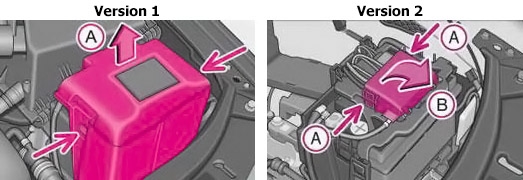
- Opening the cover: Press together the interlocks of the fuse cover simultaneously in direction of the arrow (A) and fold down the cover in direction of the arrow (B).
- Closing the cover: Closing the cover takes place in the reverse order.
On some vehicles, the battery cover must be removed before removing the fuse cover link.
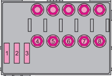
| № | Power consumer | A |
|---|---|---|
| 1 | Pump for ABS | 30 |
| 2 | Valves for ABS | 30 |
| 3 | Radiator fan 1st stage | 30 |
| 4 | Glow plugs for heating the coolant, relay for secondary air pump | 50 |
| 5 | Engine control unit | 50 |
| 6 | Radiator fan 2nd stage | 40 |
| 7 | Main fuse of the interior | 110 |
| 8 | Dynamo | 110 / 150 (*a) |
| a) Depending on the engine type and equipment | ||
Advertisements